TM 10-4610-232-12
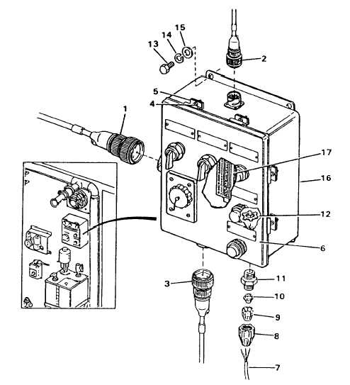
Figure 4-33. Switch Panel No. 2
DISASSEMBLY.
a. Tag and disconnect all wires to fan and mixer switches (4, Figure 4-34), light switch (9), two alarms (20) and
receptacle (18) at the component end and at the terminal board (36).
b. Remove handles with nuts (1), lock ring (2), switch (4), and spacers (5).
c. Remove nut (6), lock ring (7), switch (9), three spacers (10) (11) DELETED.
d. Remove capscrew (12) and dust cap (13).
e. Remove four capscrews (14), nuts (15), Iockwashers (16), washers (17) and remove receptacle (18).
f. Remove two nuts (19), two washers (19A), six spacers (19B) and two alarms (20).
g. Remove wiring harness (21) as follows:
(1) Tag and disconnect wires to terminal board (36).
(2) Remove four capscrews (22), nuts (23), Iockwashers (24) and washers (24A).
4-142 Change 2