
TM 10-4610-240-24
TM 08580C-24/2
TO 40W4-13-22
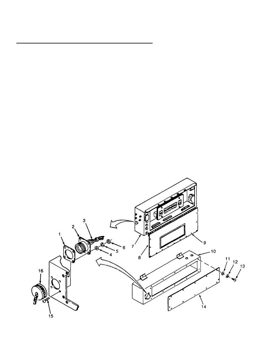
3-45. CONTROL BOX ASSEMBLY MAINTENANCE - continued.
RECEPTACLE CONNECTORS
NOTE
All receptacle connectors in the control box and junction box assemblies are removed
and installed the same. One receptacle connector is shown as typical.
Wires must be soldered to pin connections as tagged.
a.
If working on control box assembly, remove 14 screws (13), lockwashers (12), and flat washers (11). Lower
control box cover (14).
b.
c.
Position gasket (1) on box (10) or (7) and position receptacle connector (2) in box cutout.
d.
Install four screws (15), flat washers (4), new lockwashers (5), and nuts (6).
e.
Install cap (16) on receptacle connector (2).
f.
If working on control box assembly, install control box cover (14). Install but do not tighten 14 screws (13),
lockwashers (12) and flat washers (11)
g.
If working on junction box assembly, close junction box cover (8) and secure 13 rotary
3-261

