TM 10-4610-241-10
TO 40W4-13-41
2-8. INITIAL ADJUSTMENTS AND CHECKS - cont.
f.
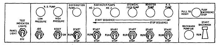
Control Box Switches. Refer to figure 2-48.
(1)
Check position of switches on the control box assembly. If you find any switch in the RUN position, set it to
STOP, with the exception of the BACKWASH switch that will stay in the RUN position.
NOTE
The switches marked START are spring loaded. Upon release they return to the middle (RUN)
position. The ones marked JOG, RESET, and START BACKWASH return to the normal position
when released.
(2)
An indicator lamp is associated with each switch except for the EMERGENCY STOP button. Check the
setting of the EMERGENCY STOP button. Pull button until it remains out when released. This is the
normal operating position.
Figure 2-48. Control Box Switches.
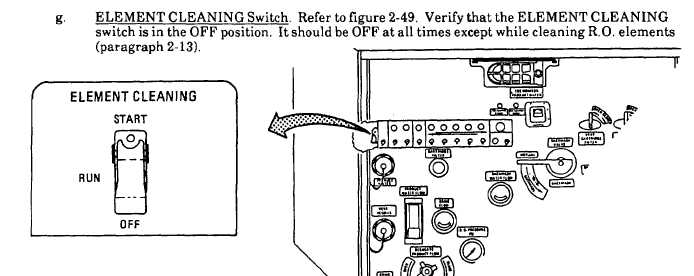
g.
ELEMENT CLEANING Switch. Refer to figure 2-49. Verify that the ELEMENT CLEANING switch is in the PFF
position. It should be OFF at all times except while cleaning R. O. Elements (paragraph 2-13).
Figure 2-49. Element Cleaning Switch.
2-83