TM 10-4610-241-24
TO 40W4-13-42
3-49.
CONTROL BOX ASSEMBLY REPAIR.-continued.
(2)
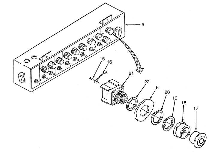
Emergency stop switch.
(a) Position rubber washer (22) and switch body (21) in cutout on control box assembly (5).
(b) Install fiber washer (20), keyway washer (19), locknut (18) and cap (17).
NOTE
Wire tags may be lost or become illegible. If this occurs, consult electrical
interconnection diagram, Appendix F, or data plate on door of junction box for
connection information.
(c) Install wires (16) as tagged, or use electrical interconnection diagram, and secure with two screws (15).
3-287