TM 10-4610-241-24
TO 40W4-13-42
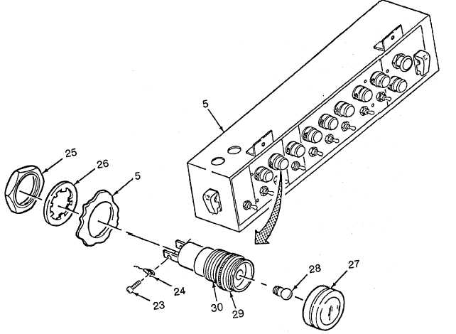
3-49.
CONTROL BOX ASSEMBLY REPAIR.-continued.
(3)
Indicator lampholders.
NOTE
There are nine lampholders. All are installed the same way. One is shown.
(a) Install bulb (28), flange (29) and lens (27). Allow about 1/8 inch between flange and lens when installed.
(b) From front of control box assembly (5), position lampholder (30) in cutout on control box (5).
(c) Install lockwasher (26) and nut (25).
NOTE
Wire tags may be lost or become illegible. If this occurs, consult electrical
interconnection diagrams, Appendix F or data plate on door of junction box for
connection information.
(d) Install three wires (23) as tagged, or use electrical interconnection diagrams, and secure with two screws
(23).
3-288