TM 10-4610-246-13
4.21
MAINTENANCE OF PUMPER ASSEMBLY - (Cont)
NOTE
Threaded stud may stay in either diaphragm and
must not be discarded.
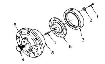
(c) Unscrew chemical side diaphragm
(6) and remove.
Protect threads when removing stud.
(d) Unscrew stud (7).
Figure 4-12. Pumphead
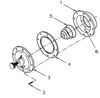
(2) Remove water side diaphragm.
(a) Turn stroke adjusting knob (4) CCW
until dial scale (5) reads 10.
(b) Place small end of cylinder (1) face
down on workbench.
NOTE
Put a realignment mark on cylinder flange.
(c) Remove all but two capscrews (2)
which will be opposite each other.
Maintain pressure on the water side diaphragm
flange when removing it during maintenance. The
water side diaphragm is under spring pressure.
Uncontrolled release may cause injury to personnel.
(d) Push flange (3) down to relieve spring pressure and remove remaining two capscrews (2) slowly.
(e) Slowly lift flange (3) off, releasing spring
pressure.
(f) Remove water side diaphragm (4).
4-21
Figure 4-13. Water Side Diaphragm