TM 10-4610-246-13
4.21
MAINTENANCE OF PUMPER ASSEMBLY - (Cont)
(g) Remove spring (5).
(3)
Remove dial scale assembly.
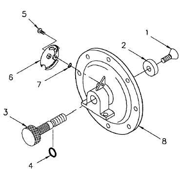
(a) Remove pad retaining screw (1, Figure 4-14)
and pad (2).
(b) Remove stroke adjusting knob (3).
(c) Remove preformed packing (4) from stroke
adjusting knob (3).
(d) Remove screw (5), dial scale (6), and star
washer (7) from flange (8).
c.
Inspect.
(1) Clean all components with soapy water.
(2) Inspect diaphragms for tears, holes, or
brittleness. If damaged, replace.
(3) Inspect dial gear for bent, damaged, or missing
teeth. If damaged, replace.
(4) Inspect stroke adjusting knob (4, Figure 4-12) for damaged threads, and spline gear. If damaged, replace stroke
adjusting knob.
(5) Inspect pumphead (3) for cracks or damage. If damaged, replace.
d.
Repair.
Repair is accomplished by replacement of damaged parts.
e.
Assembly.
(1) Install star washer (7), dial scale (6, Figure 4-14), and screw (5).
(2) Install preformed packing (4) onto stroke adjusting knob (3).
(3) Install stroke adjusting knob (3) into flange (8).
(4) Install pad (2) and screw (1) on stroke adjusting knob (3).
(5) Position spring (5, Figure 4-13) and waterside diaphragm onto cylinder (1).
NOTE
Drain hole is to be positioned at the bottom of the pumper assembly when installed.
(6) Place flange (3) over water side diaphragm (4) with mounting base on flange aligned with drain (6).
4-22
Figure 4-14. Dial Scale Assembly