TM 5-4610-218-34
ders through four aspirators (fig. 14), from
ited storage of coagulated water, and serves as a
where it overflows into the downcomer tube, or
sump for the suction of the filter pump. It con-
tains an overflow pipe, to permit operation of
mixing zone.
the erdlator at the rated capacity when the fil-
(4) Effluent launder. The effluent launder is
ters are stopped. A drain in the bottom of the
a one piece, circular-shaped aluminum through
wet well permits complete drainage of the tank
that surrounds the downcomer tube. It is at-
to waste when water unsited for faltering is ob-
tached to the bridge rail assembly by three ad-
tained from the erdlator.
justable support rods. It collects the clear water
(6) Sludge concentrator tank. The sludge
from the upper section of the erdlator tank and
concentrator tank is welded externally to the
discharges it into the wet well tank.
front of the wet well tank. It is a square, funnel-
(5) Wet well tank. The wet well tank is
shaped aluminum tank with a shorter circular
made of aluminum, and consists of a triangular
tank welded to the inside of it. There is an inlet
section welded to the rear quadrant of the er-
inside of the main tank near the bottom which
dlator tnak for the collection of the effluent from
permits the woolly slurry to enter by gravity.
the erdlator. The capacity of the wet well tank is
The inner tank has an opening in the bottom,
approximately 150 gallons. It provides for lim-
controlled by a manually-operated plug valve to
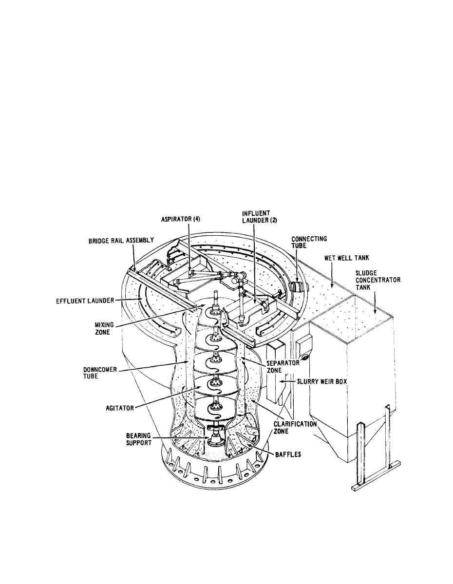
Figure 1-4. Cross Section of the Erdlator Assembly
1-7


