TM 55-1930-209-14&P-12
11.
Switch to the low power mode.
12.
Adjust R604 to obtain a 0.7 watt reading on the wattmeter.
13.
Connect the tone generator to pins #2 and #3 of JMO1.
14.
Set the output of the generator to 1 kHz, 20 mV.
15.
Switch to the high power mode.
16.
Key the transmitter and adjust RM28 to obtain4.5 kHz deviation.
17.
Reduce the tone generator output level to obtain3.0 kHz deviation.
18.
Increase the level by 20 dB and adjust RM28 to obtain4.5 kHz deviation.
III.
Receiver
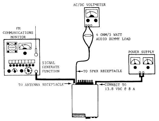
Prior to alignment of the receiver, connect test equipment as shown in Figure 9.
1.
Select channel 06.
2.
Connect a zero center meter to T13.
3.
Adjust the volume for a 1.4 VAC voltmeter reading.
FIGURE 9. RX TEST SET-UP
18