MANUAL RELEASE (See Figure 5)
To manually release the brake, rotate release knob (21)
clockwise until it strikes stop pin (22). The brake will
remain in the release position until manually reset, or
automatically reset when electric power is restored.
MAINTENANCE AND SERVICE
FRICTION DISC REPLACEMENT (See Figure 5)
When total wear on rotating friction disc reaches
1/16',;replace as follows:
Remove cover. With release knob (21) in released
position, remove three mounting screws (27) and-
remove operator assembly (6) as a unit Spring (5). is a
loose part. Avoid loss. Remove stationary discs (3),
install new rotating discs (4) and reassemble all parts in
reverse order. After starting three screws (27), turn two
wear adjustment screws (26) counterclockwise to allow.
the three posts on end plate assembly (7) to seat
against the bracket (2). Tighten screws (27). Readjust
magnet gap (see WEAR ADJUSTMENT). Replace
cover.
MAGNET ASSEMBLY REPLACEMENT
Remove cover. Unscrew two flat head screws (13),
remove shoulder nuts (12) and rubber washers (11).
Remove and replace magnet assembly (9) and
reassemble' parts in reverse order. Magnet and
armature faces must be clean and parallel to insure
quiet operation (see WEAR ADJUSTMENT -' and
TROUBLE SHOOTING). If manual release does not
operate properly, see TROUBLE SHOOTING.
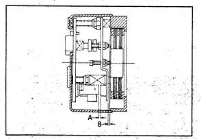
Figure 3. Brake Cap Adjustment
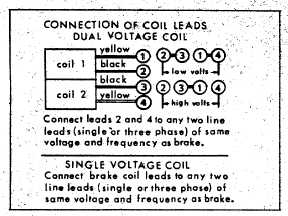
Figure 4. Wiring Diagram
WEAR ADJUSTMENT (See Figure 3)
When armature plate (25) touches bracket (2), closing
gap "B,' adjustment for friction disc wear is required.
Turn two screws (26) clockwise until magnet gap 'A"
reads .040" to .045" at narrowest gap, for 1 and 2 disc
'models, and reads .050" to .055" at narrowest gap, for 3
disc models. Any delay in adjusting gap will result in
eventual loss of torque.
TORQUE ADJUSTMENT
The 60 Series Brake is factory set for rated static torque.
To increase stopping time and lower torque, turn two
.locknuts above torque springs (16) counterclockwise,
increasing spring length. Each full turn decreases
torque by approximately 10%. Do not adjust brakes for
higher torque, as this will cause premature coil burnout.
TROUBLE SHOOTING
BRAKE DOES NOT RELEASE
Check for failure of power supply to brake.
Check brake visually for broken or damaged parts.
Check for broken leadwire or bad electrical connection.
Check for correct voltage. Voltage must correspond to
that listed on brake nameplate. If voltage is
more than 10% below figure stamped on
nameplate, magnet will not pull in, causing coil
to burn out within minutes. If voltage is more
than 10% above, coil will overheat and burn out.
Check for burned out coil (coil may be charred or
burned).
BREAK DOES NOT STOP
Check that manual release is in normal reset position.
Check brake visually for broken or damaged parts.
Check disc wear (See WEAR ADJUSTMENT).
Check for broken friction disc.
Make certain hub has not shifted position on shaft and
that all rotating discs are fully engaged on hub.
BRAKE CHATTERS OR HUMS
Clean magnet faces if dirty. Insert a clean sheet of
paper between magnet faces and energize brake. Move
paper around between faces to dislodge dirt. Finally,
remove paper.
Check that magnet faces are parallel in closed position.
1.
If not parallel along length of magnet, check
bushings (14) under torque springs for binding
or excessive wear.
2.
If not parallel across width of magnet, adjust
pivot nut (8) on post to obtain minimum magnet
hum. After adjusting pivot nut, lock in place
with nut (item 7, part "C"). Check magnet gap
"A" and adjust if necessary (See WEAR
ADJUSTMENT ). Operate manual release (21)
and adjust if necessary.
Check if shading coil (10) is cracked, broken or out of :
position. Replace magnet assembly if cracked
or broken.
Check for low voltage. Magnet will not pull in and coil
will burn out if voltage is more than 10% below
figure stamped on nameplate.
MANUAL RELEASE DOES NOT WORK Check for
broken or damaged parts.
Check return spring (24). Brake will not reset
automatically if this spring is broken.
Check magnet gap "A" with knob in released position.
Gap must be .030" at narrowest point. If gap is too
wide, motor shaft will not turn freely. If gap is too small,
knob will not return automatically when power is applied.
Adjustment for correct magnet gap is made by turning
nuts (18 and 19). Make sure nuts are tight against
armature
plate
(25)
after
adjusting
release.