SECTION E - REPLACEMENT PARTS LIST
Ordering Instructions
The following information must accompany all
correspondence or replacement parts orders:
1.
Hoist model
2.
Serial number of hoist
3.
Voltage, phase, hertz
This information is marked on the hoist
identification plate.
When ordering trolley parts, also specify the
trolley capacity.
For parts orders specify:
1.
Quantity desired
2.
Key number of part
3.
Part name
NOTE: When ordering replacement parts, it is
suggested that the individual also consider the need (if
he has not done so already) for such items as gaskets,
fasteners, etc. These items may be damaged or lost
during disassembly or may be just unfit for future
service because of deterioration from age or service
conditions.
The parts shown on pages 29-38 are for current
hoists and trolleys. Additional parts which were used on
older units are listed on pages 40-54.
Assembly Instructions
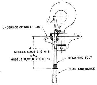
HOOK OR LUG SUSPENSION - Models E, H, R,
RR, E-2, H-2, R-2 and RR-2.
Assemble the dead end bolt and block through
the suspension adapter as shown in Figure 16.
CENTRIFUGAL MECHANISM
Centrifugal Mechanisms (S-430) are furnished
in kit form which contains the centrifugal mechanism,
spacers and an Instruction Sheet. The Instruction Sheet
provides complete details on the installation of the
replacement mechanism.
To install the replacement mechanism, a press-
on tool (shown in Figure 17) will be required. The press-
on tool is not included in the kit, however, it may be
ordered from the Factory order Centrifugal Mechanism
Press-On Tool Key No. S-438.
When installing the replacement mechanism,
the spacer is placed between the rotor shaft shoulder
and the centrifugal mechanism as shown in Figure 18.
Using a slow-acting press, apply pressure to the press-
on tool and press the mechanism onto the shaft until it
sets against the spacer. To prevent damaging the
mechanism and/or spacer, the force applied to the
press-on tool to press the mechanism onto the shaft
should not exceed 3000 pounds.
FIGURE 16.
HOOK SUSPENSION.
FIGURE 17.
CENTRIFUGAL MECHANSIM PRESS-ON TOOL. 27
27