MOUNTING THE NEW HARDWARE
•1.
Re-check the series number on the control
feedback link to ensure that it is compatible with
the pump. If the control is an MCV106AX9XX
(i.e., control less linkage assembly), follow the
procedure outlined below to install the linkage:
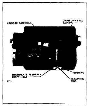
A.
Unscrew the bushing, using care not
to damage its O-ring. See Figure 6.
B.
Install the new linkage assembly
shaft
through
the
swashplate
feedback shaft hole. Place the ball
in the crosslink ball cavity.
C.
Lubricate the shaft O-ring and
replace the bushing over the shaft.
Torque to the body (10-15 foot-
pounds) so that the feedback shaft
extends through the bushing.
D.
Install the retaining ring in the
groove on the shaft.
•2.
Align one end of the replacement drag link with
the holes in the swashplate link arms.
•3.
Insert the press fit pin through the case drain
port to trap the drag link in the swashplate
clevis. It will be necessary to tap the pin into
place until the head of the pin is flush to the
clevis.
•4.
Install the retaining ring by forcing it onto the
tapered end of the pin until it locks into the
recess on the pin shaft. Again, use caution not
to drop any components into the pump housing.
•5.
One .042.inch diameter orifice must be installed
in the supply passage on pressure override-
compatible valves. (See Ordering Information.)
For all others, a .042-inch diameter orifice may
be installed in the supply passage if reduced
swashplate response is desired.
•6.
Engage the pin on the control in the drag link
and swing the control into place against the
pump housing. The drag link should be on the
cylinder block side of the swashplate. Install the
seven mounting screws and tighten to 10-11
foot-pounds of torque.
•7.
Connect the pipe or tubing from the control
handle into the C1 and C2 ports (9/16-18 UNF
threads per SAE J514). Phasing of the HDC is
such that a pressure rise at the C2 port causes a
pressure rise at the A output port of the pump,
given a clockwise
pump prime mover
rotation as viewed into the input shaft.
PUMP NEUTRAL ADJUSTMENT
USE THE FOLLOWING PROCEDURE TO BRING THE
PUMP TO NEUTRAL ONCE THE HYDRAULIC DIS-
PLACEMENT CONTROL HAS BEEN MOUNTED.
•1.
Install a 300 psi gauge into the charge pressure
gauge port on the pump. See Figure 7.
•2.
Using a 9/16-inch wrench, loosen the hex lock
nut on the null adjustment screw. See Figure 1.
• 3.
Set the hydraulic control handle to neutral,
• 4.
Start the prime mover and run at low idle.
• 5.
Warm the system up for several minutes to
bleed air.
• 6.
Slowly increase the prime mover speed to rated
rpm.
FIGURE 7. Location of pump ports.
PUMP NEUTRAL ADJUSTMENT (continued page 7)
Sundstrand Mobile Controls
95-8972
6