IS3100-1
1/84
REGULATOR
INSTRUCTION SHEET
AIR LINE REGULATORS-SERIES 1500
Standard Units-Relieving
"NR" Designates-Non Relieving
Maximum Supply Pressure-300 PSI
Operating Temperature Range-40F to 120F
INSTALLATION - Install regulators so the airflow is in
the direction “IN-OUT” as indicated on the head of all
units. Regulators should be installed downstream from
filters or upstream from lubricators, but as close as
possible to the pneumatic tools or appliances being
serviced. The regulator will accurately control secondary
pressure between 2 and 125 P.S.I., maximum primary
pressure 300 P.S.I. The selfbleed feature permits use
on dead-end applications.
WARNING - Units are die cast aluminum, do not over
torque when installing regulator or gauge. Use of
Teflon tape is not recommended.
OPERATION ADJUSTMENTS - After the regulator is
installed, back off pressure adjusting screw before the
air is turned on. This will relieve compression on the
regulating spring. Turn on the air supply and regulate
the adjusting screw until the pressure gauge shows the
desired pressure.
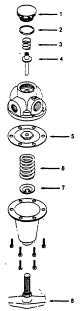
MAINTENANCE - On detection of air leaks, pressure
fluctuation, or 'creep"; depressurize system and remove
back cap. Inspect valve seat for damage or wear.
Inspect seat In head casting for foreign material or
damage. Clean with kerosene and blow out with air.
Replace any damaged parts.
If leaks persist; remove bonnet, Inspect diaphragm and
diaphragm seat for wear or foreign material. Replace
damaged or worn pats.
WARNING! For compressed air service only. Not to
be used on life support systems.
NR-Non Relieving
ID#
Kit Description
Kit Part Number
Contents
1/4,3/8
1/2
3/4,1
8
Adjusting Screw
AK1582S
AK1584S
AK1586S
Adjusting Screw and Nut,
Std. Handle
AK1582P
AK1584P
AK1586P
Adjusting Screw and Nut,
Panel Handle
1, 2, 3,
Repair Kit
RK1582R
RK1584R
RK1586R
Relieving Diaphragm, Disc Ass'y,
4, 5
Bottom Plug “O" Ring.
Bottom Spring
RK1582NR
RK1584NR
RK1586NR
Non-Relieving Diaphragm Ass'y,
Disc Ass'y, Bottom Plug
“O" Ring, Bottom Spring
5, 6, 7
Adjusting Spring
SK1582S
SK1584S
SK1586S
2-125 PSI Adjusting Spring,
Spring Button.
SK1582LP
SK1584LP
SK1586LP
2-50 PSI Adjusting Spring and
Spring Button
SK1582HP
SK1584HP
SK1586HP
10-200 PSI Adjusting Spring and
Spring Button