TM 10-4610-241-10
TO 40W4-13-41
CHAPTER 2
OPERATING INSTRUCTIONS
section L
Description and Use of Operator’s Controls and Indicators
section II
Preventive Maintenance Checks and Services
Section III
Operation Under Usual Conditions
Section IV.
Operation Under Unusual Conditions
Section I. DESCRIPTION AND USE OF OPERATOR’S CONTROLS AND
INDICATORS
Page
ROWPU Controls and Indicators.. . . . . . . . . . . . . . . . . . . . . . . . . . . . . . . . . . . . . . . . . . . . . . . . . . . . . . . . . . . . . . . . . .
2-4
Trailer Controls and Indicators(Models WPES-10 and H-95 18- 1) ...................................................
2-1
2-1. TRAILER CONTROLS AND INDICATORS (Models WPES-10 and H-9518-1).
a.
Electrical Connector. The only indicators on the flatbed cargo trailer are the stop lights, tail lights,
and the blackout light assembly: ‘These lights are powered and controlled from the towing vehicle.
The plug on the trailer electrical cable (figure 2-1) makes the electrical system operational.
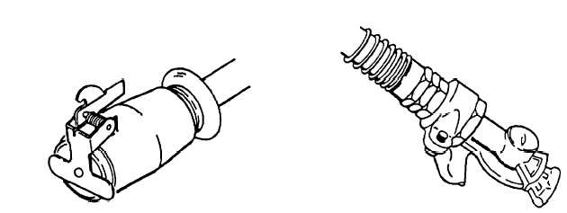
b.
Air Brake Connectors. Two air hoses connect the trailer brakes to the towing vehicle brake system
with glad-hand connectors (figure 2-2). When the trailer is not connected to the towing vehicle, the
connectors are stowed on dummy couplers on the trailer to prevent damage and contamination.
CAUTION
Do not attempt to move trailer without releasing air brakes, brakes are locked.
Figure 2-1. Trailer Electrical Plug.
Figure 2-2. Trailer Air Hose Glad-Hand Connectors.
Change 2 2-1