
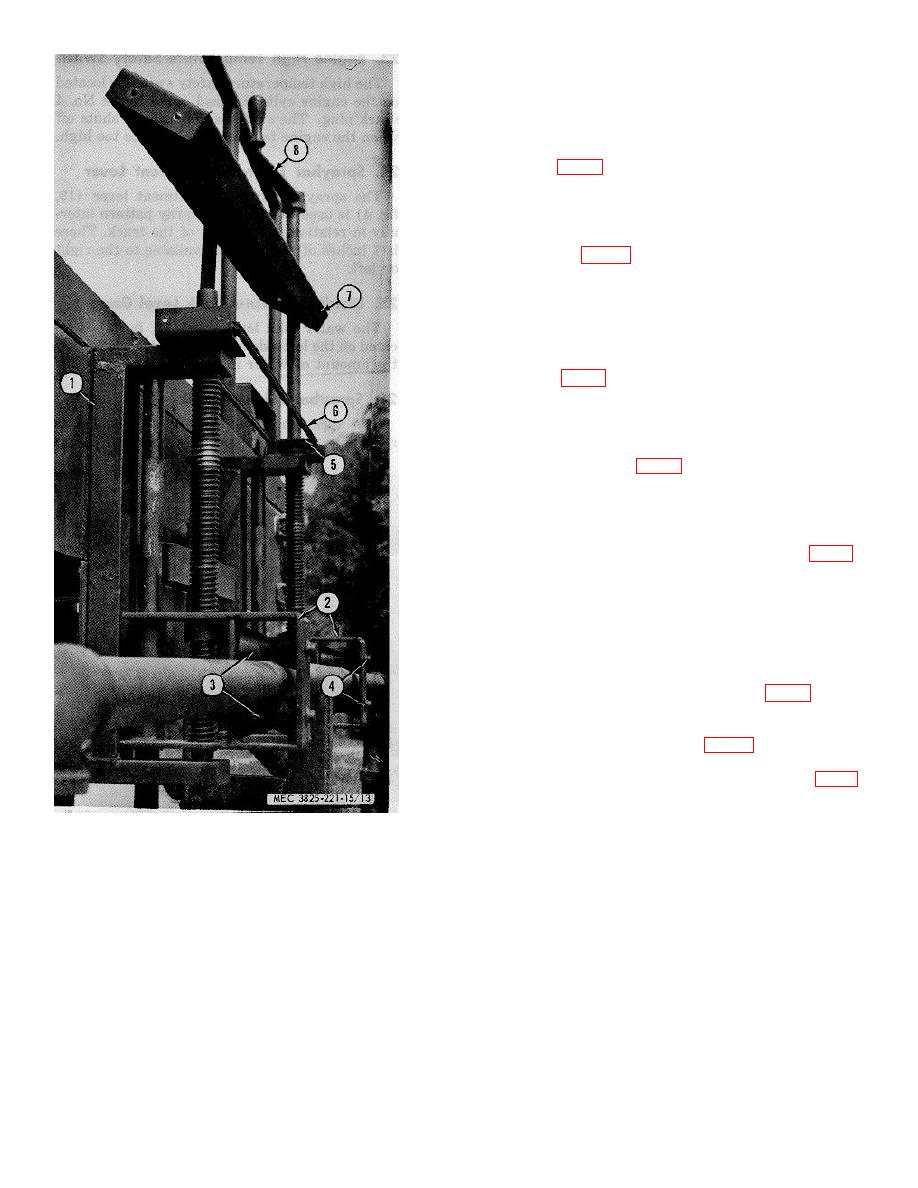
used for vertical adjustment of the spray bar position. An
adjustment of 10 inches is made possible by the use of jack screws.
27. Spraybar Valves Control Levers
The distributor is provided with a valve for each side of the
spraybar (15 and 16, fig. 4). These valves may be controlled
independently or together. Moving the levers to the extreme left
position opens the valves to maximum discharge.
28. Discharge Valve Control Lever
The discharge valve (15, fig. 11) is located beneath the operator's
platform and is operated from the operator's platform. Moving the
lever to the right opens the valve, permitting gravity flow from the
tank to the spraybars. When pumping water through the spraybars
this valve should be closed.
29. Suction Valve
The suction valve (17, fig. 4) is located adjacent to the pump inlet
tee. The operating lever is mounted on the valve. This valve
should be closed when pumping from supply other than the tank.
30. The Discharge Pressure Gage
The discharge pressure gage (20, fig. 4) is located in the discharge
line. It indicates the water pressure being discharged from the tank
to the spraybars or the fire hose.
31. Signal Gongs
A signal gong is provided at each end of the water tank (4, fig. 2).
These are to be used by the driver and operator to signal each
other in order to coordinate the operation of the truck and water
distributor. A pull cord is accessible to the driver that rings the
gong at the rear of the tank and the forward gong is operated by a
pull cord accessible from the platform.
32. Bitumeter Assembly
The bitumeter assembly consists of a tachometer (1, fig. 5)
attached to the instrument panel inside the cab of the carrier and a
drive cable (6) running from the tachometer (1) through the
floorboard of the carrier cab to the frame (9, fig. 29) of the fifth
wheel, where the bitumeter drive (5) is located. The fifth wheel
is located on the underside of the carrier, and the lift rod (3, fig. 5)
used for lowering or raising the fifth wheel is located inside the cab
of the carrier.
1 Takeup bracket
6 Sprocket
2 Roller bracket
6 Chain
3 Roller
7 Guard
4 Retainer
8 Vertical adjustment crank
Figure 13. Spraybar takeup assembly.
AGO 6871A
16