TM 55-1930-209-14&P-12
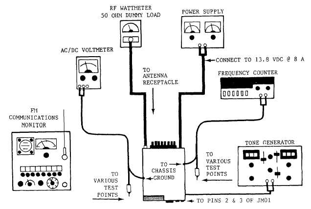
FIGURE 6. PLL, TX TEST SET-UP
II.
Transmitter
Prior to alignment of the transmitter, connect test equipment as shown in Figure 6.
1.
Select channel 16.
2.
Switch the radio to the low power mode.
3.
Lower the supply voltage by 20% (to approximately 11 VDC).
4.
Preset variable resistors R603 and R604 to their maximum counterclockwise positions.
5.
Connect the voltmeter, set for DC volts, to T52.
6.
Adjust C505 to obtain the maximum voltmeter reading.
7.
Preset C514, C522, C531, and C541 to center position.
8.
Adjust C514, C522, C531, and C541, in that order, to obtain maximum reading on the wattmeter.
9.
Reset the power supply voltage to 13.8 VDC and switch to the high power mode.
10.
Adjust k603 to obtain a 24 watt reading on the wattmeter.
15