TM 55-1930-209-14&P-12
d.
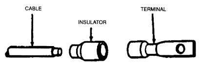
When replacing electrical components, follow proper procedures for soldering in TB SIG 222. Crimp connections
as shown in Figure 2-11. Check all grounding. Make sure current carrying members are properly insulated to
avoid short-circuiting. Check for abrasions and chafing of insulation on wires and cables. Repair with tape or
replace as necessary.
WARNING
To prevent electrical shock, either disconnect equipment power cord or open applicable circuit
breaker to branch equipment circuit. Redtag circuit breaker with: "WARNING-DO NOT ACTIVATE.
REPAIRS BEING MADE." Also, when cleaning, repairing, or replacing Army radio antenna, redtag
Army radio to prevent operation and transmission.
(1)
Strip cable insulation equal to depth of terminal well.
(2)
Slide insulator (if used) over cable.
(3)
Insert cable into terminal well and crimp.
(4)
Slide insulator (if used) over crimped end of terminal.
Figure 2-11. Replacement of Crimped Terminals
NOTE
Due ,mission and crew capabilities of this vessel, maintenance normally assigned to higher
echelons may be assigned to the crew.
2-18.1 Cleaning. Clean and touch up components.
2-18.2 Fuse replacement. Replace fuses listed in step 2-11b as necessary.
2-18.3 Indicator lamps. Replace indicator lamp when burned out.
2-18.4 Cable replacement. Check and replace all interconnecting cables as follows.
WARNING
Disconnect power cord or open appropriate circuit breaker before replacing cable.
a.
Disconnect cable and redtag connector/receptacle.
b.
Check connectors at both ends of cable for looseness or bent pins. Secure connectors and straighten pins as
necessary.
c.
Check cable for continuity.
d.
Install repaired or new cable Make sure connections are secure.
e.
Check to ensure satisfactory operation.
2-22