ASSEMBLY INSTRUCTIONS
SWING JOINTS
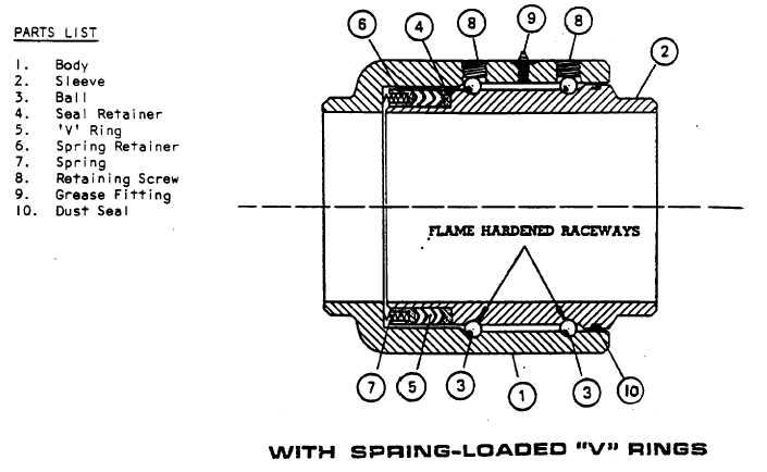
Note that the last coil of the springs (7) has been upset (o.d. slightly larger). When the upset
end is inserted into the holes provided in the spring retainer (6) the springs remain secure. Place
the assembled unit (spring end first) into the body (I) bore. Place the set of three 'V' rings (5)
onto spring retainer in body. The 'V' rings must be installed with the sealing lips facing toward
the direction of pressure.
Set dust seal (10) into 'O' ring groove on sleeve (2). On the opposite end place the seal retainer
(4) over diameter on sleeve with chamfered end facing the 'V' rings.
Insert sleeve unit into body bore, compressing swing joint together until ball races of both body
and sleeve are in line. (DO NOT ROTATE EITHER UNIT WHILE COI1lPRESSING.) Care
should be taken to avoid pinching or tearing 'V' rings. Drop balls (3) into raceways through
loading holes, rotating sleeve as you load. After a complete set of balls have been installed,
assemble ball retaining screws (8).
Grease Swing Joint as required through grease fitting (9). If grease fitting does not have a
pressure relief feature, do not over-grease as you might create a pressure lock and the Swing
Joint will not rotate.
All seals and their contact surfaces should be lubricated for ease of assembly.
The Swing Joints are shipped completely assembled and ready for service. However, if you
need to disassemble the unit, reverse the procedure described. After fabricating end styles re-
assemble per instructions.


