WOODWARD PSG GOVERNORS
SYSTEMS OPERATION
PSG GOVERNOR
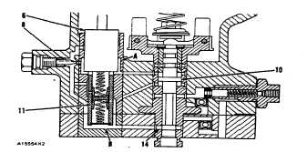
6. Power piston. 8. Needle valve. 10. Pilot valve
compensating land. 11. Buffer piston. 14. Control
ports. A. Chamber. B. Chamber.
As power piston (6) moves in the direction of the
drive unit the volume of chamber (A) decreases. This
pushes the oil in chamber (A) into the chamber above
buffer piston (II11). As the oil from chamber (A) flows
into the power piston it moves the buffer piston down in
the bore of the power piston. The pressure at chamber
(A) is more than the pressure at chamber (B).
Chambers (A and B) are connected respectively to
chambers above and below the pilot valve compensating
land (10). The pressure difference felt by the pilot valve
compensating land adds to the force of the speeder
spring to move the pilot valve down and close the control
ports. When the flow of oil from chamber (B) stops so
does the movement of the fuel control linkage.
Hunting
There is a moment between the time the fuel control
linkage stops its movement and the time the engine
actually stops its increases or decrease of rpm. During
this moment there is a change in two forces on the pilot
valve, the pressure difference at the pilot valve
compensating land and the axial force of the flyweights.
The axial force of the flyweights changes until the
engine stops its increase or decrease of rpm. The
pressure difference at the pilot valve compensating land
changes until the buffer piston returns to its original
position. A needle valve (8) in a passage between space
(A) and (B) controls the rate at which the pressure
difference changes. The pressure difference makes
compensation for the axial force of the flyweights until
the engine stops it increase or decrease of rpm. If the
force on the pilot valve compensating land plus the axial
force of the flyweights is not equal to the force of the
speeder spring the pilot valve will move. This movement
is known as hunting (movement of the pilot valve that is
not the result of a change in load or desired rpm of the
engine).
The governor will hunt each time the engine actually
stops its increase or decrease of rpm at any other rpm
than that desired. The governor will hunt more after a
rapid or large change of load or desired rpm than after a
gradual or small change.
PSG GOVERNOR
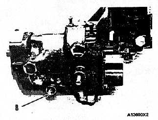
8. Needle valve.
NOTE: The Woodward PSG Governor is removed from
the engine to show the needle valve (8). When the
governor is installed on the engine, the needle valve (8)
is between the governor and the cylinder block.
SPEED ADJUSTMENT
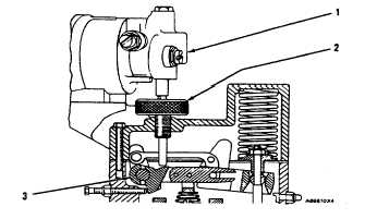
PSG governors use a clutch assembly (2) driven by
a 110V AC/DC or 24V DC reversible synchronizing motor
(1) to move link assembly (3) up or down. The clutch
assembly protects the motor if the adjustment is run
against the stops. The motor is controlled by a switch
that is remotely mounted. The clutch assembly can be
turned manually if necessary.
PSG GOVERNOR
1. Synchronizing motor. 2. Clutch assembly. 3.
Link assembly
8


