SHUTOFF AND ALARM SYSTEMS
SYSTEMS OPERATION
WATER TEMPERATURE AND OIL PRESSURE SHUTOFF SYSTEM
(WITH OIL PRESSURE DELAY OR FUEL PRESSURE SWITCH)
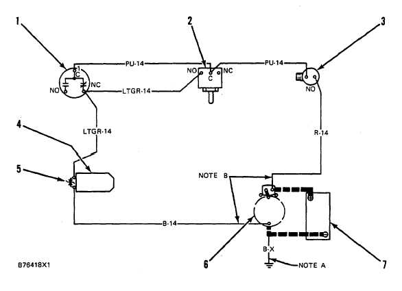
WIRING DIAGRAM
1. Oil pressure switch. 2 Water temperature contactor. 3. Oil presure (time delay) or fuel pressure switch. 4. Rack
solenoid 5. Diode assembly. Starter. 7. Battery.
If the oil pressure is too low or the coolant
temperature is too high this system will activate rack
solenoid (4). The solenoid is connected to the fuel rack
by linkage.
When it is activated it will move to stop the flow of fuel to
the engine. The engine will stop.
NOTICE
To help prevent damage to the engine, find and
correct the problem that caused the engine to
shutdown before the engine is started again.
Before the engine can be started it will be necessary to
push the manual override button on (earlier) oil pressure
switch ( ). Oil pressure will return the manual override
button to the run position.
Diode assembly (5) is used to stop arcing, for protection
of the system.
Oil pressure delay or fuel pressure switch (3) is used to
prevent discharge of battery (7) through the solenoid
when the engine is stopped.
36


