TM 55-2090-201-14&P
6-7.
SEPARATOR ASSEMBLY, TYPE A AND B (Continued).
L O C A T I O N
I T E M
A C T I O N
R E M A R K S
5.
Flow rate
Remove.
indicator
(4)
6.
Water dis- Remove.
charge
line (5)
7.
Separator
a. Attach sling around sepa-
assembly
rator assembly.
(6)
b. With the aid of a hoist,
Set on flat
remove separator assembly.
surface and
block to pre-
vent tipping
over.
c. Detach hoist and remove
sling.
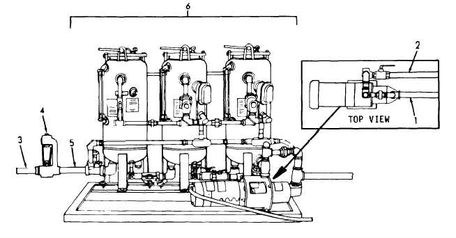
1.
Intake Line
2.
By-pass Line
3.
Flow Rate Indicator Discharge Line
4.
Flow Rate Indicator
5.
Water Discharge Line
6.
Separator Assembly
6-9