TM 10-4610-215-10
TM 08580A-10/1
Figure 2-70. Solid-State Timer (Pilot Control Valve)
(2) Solid-State Timer (Model No. 600-3). The solid state timer is approximately 8 inches high,
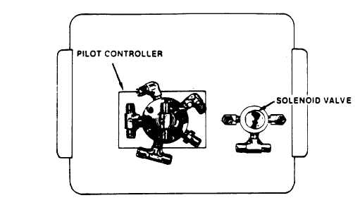
10 inches wide and 6 inches deep. Protruding from the rear of the timer is the pilot controller and solenoid valve
(fig. 2-73). Inside is a black RESET button and an INTERNAL INDICATOR knob mounted to a subpanel (view 1,
fig. 2-74).
(a) Ensure INTERNAL INDICATOR knob is in the SERVICE position by pressing the black
RESET button. The INTERNAL INDICATOR knob allows the position of the pilot controller valve to be changed
manually, which is never necessary if timer is functioning properly. In any event, if pilot controller valve is not in
SERVICE position, ROWPU cannot be backwashes using normal procedures. In fact, ROWPU will not even
operate.
(b) Overcurrent protection is provided by an internal resettable semiconductor. In the event
of an overload, the circuit breaker is reset by depressing the RESET button. If power loss erases the memory of
the time control counter, an automatic homing circuit is incorporated into the system which returns the pilot
controller to the service position whenever power is restored.
(c) Remove the subpanel to access the four 10-position rotary switches (view 2, fig. 2-74)
used to set the duration (in minutes) of each phase of the backwash cycle. Ensure settings are as follows:
Switch
Function
Recommended Setting
SW 1-
Primary Backwash
2
SW 2-
Fast Rinse
6
SW 3-
Secondary Backwash
2
SW 4-
Conditioned Rinse
2
2-73


