TM 10-4610-232-12
Table 4-2. Unit Troubleshooting Guide (Continued)
MALFUNCTION
TEST OR INSPECTION
CORRECTIVE ACTION
CHEMICAL PUMPS.
1. Chemical pump(s) do not run (Reference Schematic Diagram FO-1, Sheet 6,schematic lines 621-627).
Step 1.
Step 2.
Step 3.
Step 4.
Set the control panel up in system “NORMAL” and push the “CHEMICAL PUMP” start pushbutton.
The green “CHEMICAL PUMP ON” light should come on.
If light does not come on, notify direct support maintenance.
Remove connectors P12 and PReference Interconnection Diagram FO-2, Sheet 15) from the
side of the panel. Check for 110-120 VAC across pins J12R/J12S (poly rep), J121/J12N (product
chlorine pump). and J16A/J16B (Reference Interconnection Diagram FO-2, Sheet 9)(sequestrant
If voltage is not present for the pump(s) being troubleshoot, notify direct support maintenance.
Reconnect P12 and P16. Disconnect the connector(s) at the pump(s) being troubleshoot. Check for
110-120 VAC across the A and B pins in each connector (control panel end).
If voltage is not present, refer to the electrical schematic and replace the cable and connectors from
the control panel to the pump
that are faulty (para. 4-27).
Remove the pump control panel by removing the four corner screws and loosening the hex nut on the
stroke length knob. Check that the two fuses are not blown. Check that power leads in the pump are
tight and no corrosion is present on the connections.
(a) Replace the fuses if blown (para. 4-36)
(b) Clean off any corrosion.
Change 1
4-49
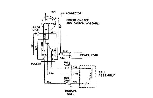
Figure 4-2. Chemical Pumps Wiring Diagram