TM 10-4610-232-12
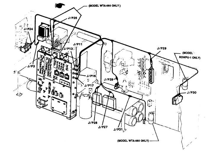
Figure 4-29. Electrical Installation (sheet I of 8) Primary Harness, Rear Wall, W-33
e.
Disconnect the cable to be removed at-each end and remove the cable.
f.
Refer to Figure 4-29, sheet 3, View, B and remove the 24 VDC input power cable as follows:
(1)
Remove cable tie wraps and disconnect cable (4) at the power supply on the ROWPU wall.
(2)
Remove nuts (1).
(3)
From outside the ROWPU, remove four screws (2) and dust cover (3).
(4)
Pull cable (4) into the ROWPU. Gasket (5) will now be free.
CAUTION
Valve actuator cable connectors are two piece connectors as shown in View C on sheet 5 of Figure 4-29.
Do not pull on the male connector when disconnecting the cable for removal. Serious damage may be
done to the valve connector. This damage will make it necessary to replace the entire valve. Always pull
on parts as shown on View C when disconnecting the cable. Grasp cable as shown and pull connector
apart.
g.
Remove the desired valve actuator cable as described in the general cable removal procedure above, with the
following exception. When pulling cable apart, grasp as shown in Figure 4-29, sheet 5, View C.
Change 7 4-125