TM 10-4610-246-13
5.7
MAINTENANCE OF UPPER AND LOWER MAIN CASE ASSEMBLY - (Cont)
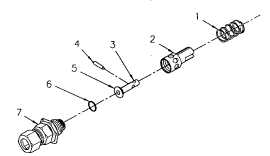
Figure 5-9. R-Valve Assembly
(a)
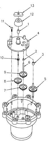
Install bearings (1 thru 3, Figure 5- 10) into gear box bearing
plate (4) by tapping gently into place with an appropriate center
punch or similar device, taking care not to force bearings or
burr edges.
(b)
Install output gear E (5).
(c)
Install idler shaft (6).
(d)
Install gear D (7).
(e)
Install gear C (8).
(f)
Install gear B (9).
(g)
Install input gear A (10).
(h)
Place gearbox bearing plate (4) in position on main case
assembly and install with three screws (11).
(i)
Install plug cock (12) and drive dog (13) handtight only. Do not
attempt to tighten drive dog at this point.
(j)
Install gasket (5, Figure 5-6), pre- formed packing (4) and
packing nut (2) into upper main case (10).
(4)
Assemble upper main case assembly.
(a)
Screw cam (1, Figure 5-6) onto cam output shaft (3) side
marked up facing up.
5-14
Figure 5-10. Gearbox