TM 10-4610-246-13
5.7
MAINTENANCE OF UPPER AND LOWER MAIN CASE ASSEMBLY - (Cont)
(b)
Place screwdriver through hole in cam (9) and tighten both cam (1) and drive dog (6) by gently turning drive
dog (6) clockwise until snug.
(c)
Position arm retainer (8, Figure 5-4) through threaded hole in upper main case (13).
(d)
Place arm (7) on arm retainer (8).
(e)
Place ball pivot (6) on arm retainer (8), ensuring that ball pivot fits into arm cradle.
(f)
Place spring (5) on arm retainer (8).
(g)
Screw arm retainer (8) into threads in housing until head bottoms out.
(h)
Compress spring (5) and place retaining washer (4) onto arm retainer (8), snapping into groove.
(i)
Install preformed packing (12) onto P-valve cap (11) and lubricate. Install P-valve cap (11) onto P-valve (10)
with needle and spring installed.
(j)
Screw P-valve (10) into threaded hole in housing until head bottoms out.
(k)
Insert R-valve (9) into hole in housing.
(I)
Back locknut on R-valve (9) away from housing.
(m)
Screw R-valve (9) into threaded hole three
turns.
(n)
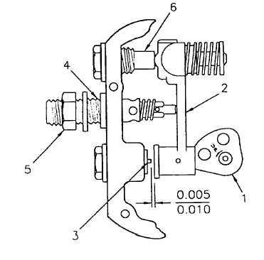
Set timing of R-valve (9) by:
1
Rotate cam (1, Figure 5-11) until arm (2)
is 0.005 to 0.010 inches from needle (3).
Hold in this position.
2
Screw R-valve (4) in until its piston just
seats. This is the point at which valve
arm (2) will just begin to move away
from face of arm retainer (6).
3
Tighten locknut (5) to hold R- valve (4) in
position.
4
Hold this position of cam (1) and check
clearance between needle (3) and arm
(2).
5
Readjust R-valve (4) if necessary to
obtain 0.005 to 0.010 inch clearance
when R-valve has just been seated.
Figure 5-11. R-Valve Timing
5-15


