TM 5-3800-205-10-2
EQUIPMENT DESCRIPTION AND DATA - CONTINUED
0002 00
LOCATION AND DESCRIPTION OF MAJOR COMPONENTS - CONTINUED
12
13
17
14
15
16
18
18
19
22
23
20
21
12
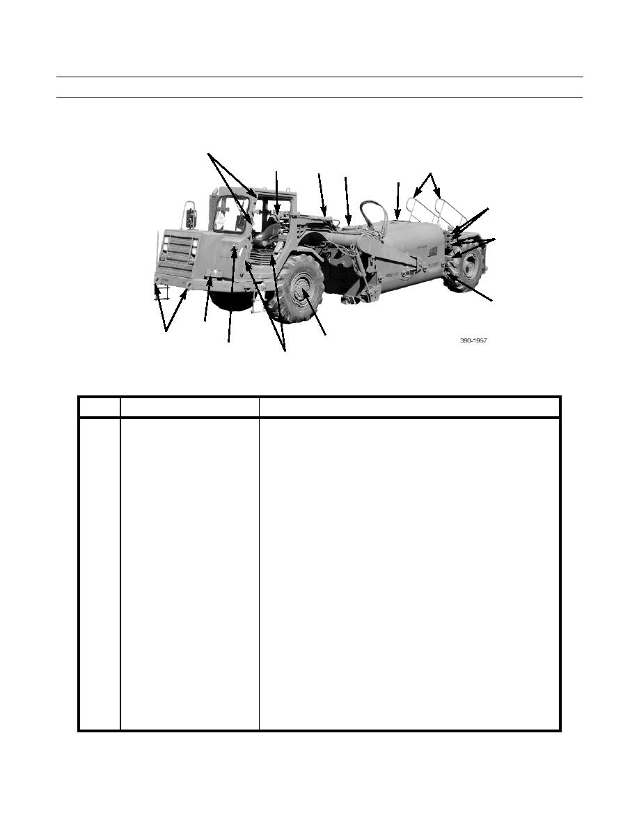
KEY
COMPONENT
DESCRIPTION
12
Grabhandles
Provide a handhold for personnel climbing on machine.
13
Hitch
Joins tractor to draft frame.
14
Steering Cylinders
Two hydraulic cylinders provide for 90-degree right or left turns with
articulated frame steering system.
15
Inspection Cover
20-inch opening allows inspection of tank interior.
16
Access Cover
20-inch opening for top loading and adding amendments to tank.
17
Handrails
Provide a handhold for personnel climbing onto tank. Can be removed
in preparation for transport.
18
Stowage Tubes
Stowage location for four suction hose lengths.
19
Suction Inlet
Camlock fitting allows attachment of pressurized water line or suction
hose during bottom loading of tank. Suction hose foot valve is stowed
at suction inlet when not in use.
20
Planetary Wheel Ends
Power front driving axle.
21
Blackout Drive Light
Used when operating in blackout mode.
22
Decontamination Apparatus
Provides mounting for portable decontamination apparatus (DAP).
Mounting Bracket
23
Towing Lugs
Provide attachment point for medium-duty towbar.
0002 00-4


