TM 5-4610-223-12
Legend for figure 2-13:
1.
Drain ventcock CV-6,
6.
Pressure gage PG-1,
1/2 in.
0 to 30 psi
2.
Gate control valve,
7.
Aspirator aeration gate control
CV-7, 1/2 in.
valve CV-11, 1 1/2 in.
3.
Main influent gate
8.
Launder leveling rods
valve CV-9, 2 in.
(3 reqd)
4.
Gate bypass valve
9.
Draincock, DC-13,
BPV-12, 1 1/2 in.
1/8 in.
5.
Aspirator aeration gate
10.
Float valve, FV-18,
control valve CV-10,
1 1/2 in.
1 1/2 in.
11.
Sensitive switch SS-1
NOTE
An aluminum measure is provided for measuring limestone. This measure is graduated from 1/2
pound to 5 1/2 pounds in increments of 1/2 pound.
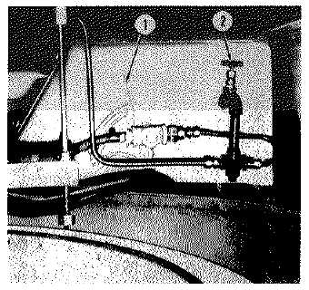
1.
Variator FEI-6, RH
2.
Gate control valve, CV-8, 1/2 in.
Figure 2-14. Chemical Slurry Feeder Controls, Side View.
(5)
Preliminary valve positioning. Valves in the water treatment section must be positioned correctly prior to
starting the water purification unit. Position valves as follows: (a) Open gate drain valve DV-25 (4, fig. 2-16) in waste
water line which drains wet well tank (7, fig. 1-3).
(b)
Close gate valves DV-19 (10, fig. 2-16) and DV-20 (9), located on waste water line near bottom of
erdlator tank.
2-30