TM 55-1930-209-14&P-12
To use the push-to-page feature, it may be necessary to add a capacitor. If the talk line impedance is established by the
M3162 Module, no additional parts will be needed. If the talk line Impedance is established by a fixed resistor, that fixed
resistor must be in series with a 10pF 25 WVDC capacitor, with the (+) end towards the talk line.
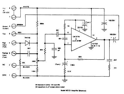
The M3131 is an integrated circuit amplifier which will turn itself off if it overheats, or if a short accidentally appears
across its output. When the short is removed, or after it cools down, the amplifier will automatically start again. If the
M3131 stops working, or works intermittently, see if the Integrated circuit, or the copper heat sink, is getting hot. It might
be caused by having a load of lower than 16 ohms, by inadequate ventilation, or by system oscillation. Oscillation may
be supersonic, in which case an oscilloscope will be necessary to detect It.
SPECIFICATIONS
The M3131 is an IC amplifier with an 80,000 ohm input Impedance. It is rated at 2 watts continuous power output into a
16 ohm resistive load, with a 24 VDC supply It also may be operated with an external 12 volt DC power source, in which
case the maximum output is 0.5 watts into a 16 ohm load. The M3131, with a gain of 32+1 dB, has an input sensitivity
of 0.13 volts rms for 5.2 volts rms output.
Capacitors are used to contour the frequency response to within +3 dB from 150-5000 Hz for best speech-to-noise ratio.
A DC supply bypass capacitor of 100uF is on each board.
Heatsinking is not adequate for loads lower than 16 ohms at rated output. Also, the output coupling capacitor will limit
low frequency response to a frequency above 150 Hz if a lower load impedance is used.
The diode coupled input is used for push-to-page operation. The diode Is back biased at 4 to 5 volts DC. When a push-
to-page button on a headset station is activated, the talk line is raised to approximately 12 VDC through a 16,000 ohm
resistor In the headset station. This forward biases the diode, and "turns on" the input. There is also a conventional
capacitor-coupled input for normal operation. Both inputs may not be used at the same time.
NOTE. A 16,000 ohm resistor Is connected between the diode-switched input and ground to establish the push-to-page
"on" bias (12 VDC) and to aid in switching the diode "off" when the DC is removed. If more than one push-to-page
amplifier Is used in a given system, this resistor must be clipped out from all but one of the amplifiers that are used in the
push-to-page mode. This resistor is located on the M3131 terminal block between pins 4 and 1.
Page 2 of 2