TM 55-1930-209-14&P-21
(10)
Install cam and balance shaft gear nut retainers with bolts and lockwasher. Tighten bolts to 35-39 Ib.-ft
torque.
(11)
Check clearance between thrustwasher and thrust shoulder of both shafts. Clearance specified is .004 to
.012 inch with new parts. (Maximum .018 inch with used parts.)
(12)
Check backlash between mating gears between .013 to .008 inch. (Maximum of .010 inch with used
parts.)
(13)
Reinstall remaining items in reverse of disassembly.
(14)
Service cooling and lubrication system as necessary.
6-28
Gear train removal and disassembly
a.
Remove engine assembly.
b.
Remove flywheel housing.
c.
Use a suitable gear puller and remove camshaft and balance shaft timing gears (para 6-22).
NOTE
Shafts do not have to be removed from block to repair or replace a gear.
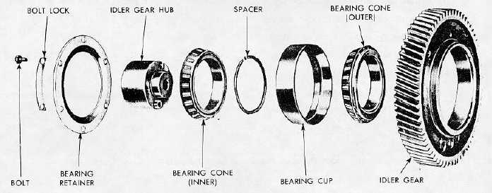
d. Refer to Figure 6-26 and remove idler gear as follows:
(1)
Remove idler gear outer thrust washer from hub.
(2)
Slide idler gear straight off hub.
(3)
Remove bolt which secures idler gear hub to block.
(4)
Remove idler gear hub and inner thrust washer as an assembly.
Figure 6-26. Idler Gear Assembly.
6-54