TM 55-2090-201-14&P
3-23.
PIPING, AIR LINES AND FITTINGS, TYPE A AND B SEPARATORS
(Continued).
LOCATION
ITEM
ACTION
R E M A R K S
1.
2.
3.
4.
5.
6.
7.
8.
9.
10.
11.
12.
13.
14.
15.
16.
17.
c. Coil
housing
(9)
d. Leads
tee
(6) and
cover
(2)
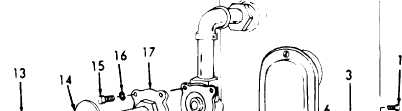
Repeat steps 8 a thru d to install sensor coil and
(4) Insert coil (13) over
end of solenoid base.
Position coil housing (9)
and nameplate (8) over coil
(13) and secure with retain-
ing cap (7).
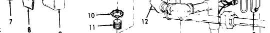
(1) Reconnect coil leads (6)
using connectors (5).
(2) Position gasket (3) in
place on tee (4).
(3) Install cover (2) on tee
(4) using screws (1).
NOTE
valve bonnet on prefilter separator.
Screws
Tee Cover
Gasket
Sensor Tee
Connectors
Coil Leads
Retaining Cap
Nameplate
Coil Housing
Locknut
Nipple
Pulling Elbow
Coil
Baseplate
Screws
Lockwashers
Valve Bonnet
3-137