ARMY TM 10-4610-309-14
MARINE CORPS TM 10802A-14/1
TACTICAL WATER PURIFICATION SYSTEM (TWPS)
0003 00
DESCRIPTION AND THEORY OF OPERATION
THEORY OF OPERATION
MICROFILTRATION (MF) SYSTEM
The Micro-Filtration system removes suspended solids (dirt) and microorganisms down to 0.2 micron,
which would foul the RO membranes possibly leading to mission failure. The MF system consist of the
MF feed tank, the MF feed tank strainer bag, the MF feed pump, the basket strainer, the MF assembly,
automatic valves to direct and control the flow through the filters for normal filtration, backwash and
cleaning and instrumentation. The MF assembly consists of 12 filter modules attached together to form a
single assembly. All of the water discharged to the MF passes through the filter fibers and is filtered.
The filtered water is called Filtrate.
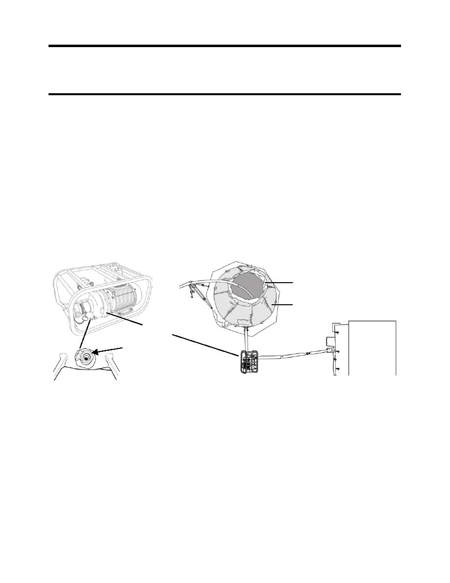
The raw feed water discharges into the inside of the MF feed tank bag filter S-1 (see Figure 3). This is a
cloth-type filter that is sized to trap seaweed fragments, which would quickly plug the basket strainer if not
removed first. The MF Feed Pump (P-3) is a motor-driven pump deployed off of the skid near the MF
feed tank. Connected at the bottom of the pump P-3 is Drain Valve V-108, which is used to drain the
pump for maintenance or at the end of the mission. The MF feed pump draws water from the tank
through the bag filter and discharges the water to the TWPS skid connection at the inlet to basket strainer
S-2.
MF FEED TANK BAG FILTER S-1
MF FEED TANK
T-1
MF FEED
PUMP P-3
TOP VIEW
DRAIN VALVE V-108
OF TWPS
Figure 3. MF System: MF Feed Tank to TWPS Skid.
From the skid inlet connection, the MF feed water passes through the basket strainer S-2, which removes
material larger than 600 micron (see Figure 4). The need to clean the strainer is indicated by the clean
strainer alarm which is activated by low-pressure or low flow during the high flow shell sweep step of
backwash. Vent Valve V-110, mounted between the strainer S-2 and valve V-111, is used as a vent
when draining the basket strainer. Valve V-110 is also used as a sample valve for measuring the raw
water conductivity. From the strainer, water flows through Automatic Valve V-111, which is open during
normal processing to provide water flow as required. Pressure Gauge PI-101 measures the feed
pressure to the MF assembly. Flow Element, FE-101, measures the MF feed flow. MF Feed Flow
Transmitter FT-101 (see Figure 5) receives the flow element output and sends flow information for display
on the Operator Control Panel (OCP). The MF feed flow splits to the upper and lower MF Feed Valves V-
112 and 113 and into the MF assembly feed channels. During operation, the Upper Feed Valve V-112 is
de-energized full open while the Lower Feed Valve V-113 is de-energized closed to an adjustable stop.
The stop is set to provide similar flow rates to the top and bottom feed channels.
0003 00-6


