ARMY TM 10-4610-309-14
MARINE CORPS TM10802A-14/1
0009 00
TACTICAL WATER PURIFICATION SYSTEM (TWPS)
PREPARATION FOR USE AND INSTALLATION INSTRUCTIONS
COLD WEATHER SET-UP OPERATION UNDER UNUSUAL CONDITIONS
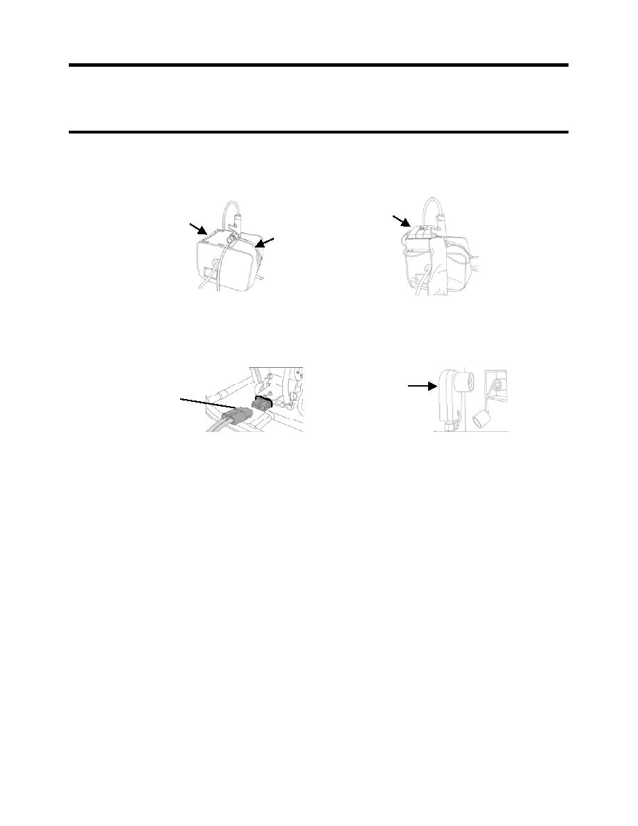
g. Set the fuel tank in place on top of the P-1 skid outside of the pump insulating cover (see
Figure 29). Complete the fuel hose connections through the opening in the cover (red-
banded supply hoses together and yellow-banded return hoses together).
FUEL
FLAP
TANK
HOOK AND
LOOP SEAM
Figure 29. P-1 Fuel Tank Installation.
h. Immediately connect the 24-volt cable first to the diesel-driven pump (see Figure 30).
i. Connect the 24-volt cable to the diesel generator 24-volt slave outlet (see Figure 30).
24-VOLT
24-VOLT
CONNECTION TO
CONNECTION
DIESEL ENGINE-
TO DIESEL
DRIVEN PUMP
GENERATOR
Figure 30. 24-Volt Cable Connection to the Diesel Engine-Driven Pump Skid.
j.
Be sure that the plug is in the pump inlet coupling.
k.
Be sure the pump drain valve is closed.
l.
Open the Adaptor A-02 Vent Valve V-102 and pour the water from the priming pitcher
into the pump. Close Vent Valve V-102.
2. Immediately start the diesel engine as follows:
a. Open the fuel cock at the bottom of the tank. (The lever points down when open.)
b. Set the engine speed lever to start.
c. Toggle the start switch (on the pump skid junction box) up and hold until the engine
starts. If it does not start after 10 seconds, wait for about 15 seconds and try again. If
the engine does not start after four tries, warm the engine for another hour before trying
to start it again.
d. Set the speed back to idle.
e. Disconnect the 24-volt cable first from the diesel generator 24-volt slave outlet.
f. Then disconnect the 24-volt cable from the diesel-driven pump.
3. Set up the P-1 pump at its final location as follows:'
a. Move the pump off of the pump insulating platform
b. Move the insulating platform to the final pump location close to the raw water source.
c. Lay an absorbent pad on the platform to absorb any oil or fuel spills.
0009 00-36


