ARMY TM 10-4610-309-14
MARINE CORPS TM10802A-14/1
0021 00
TACTICAL WATER PURIFICATION SYSTEM (TWPS)
OPERATOR INSTRUCTIONS
MICRO-FILTRATION SYSTEM CLEANING OPERATION UNDER
USUAL CONDITIONS
MF Drain
1. Drain Down #1: Drain the water from the MF as follows:
a. Stop the RO feed pump.
b. Set the Tank Heater Switch to OFF.
c. Set the System Mode switch to STANDBY.
d. Set the MF Clean Switch to DRAIN #1.
1) After a 5 second delay, the PLC automatic control purges the water from the MF
with air.
2) The PLC automatically cycles valves back to Standby at the end of the drain
down.
3) The MF CLEAN light flashes during operation and turns off when the drain down
is complete.
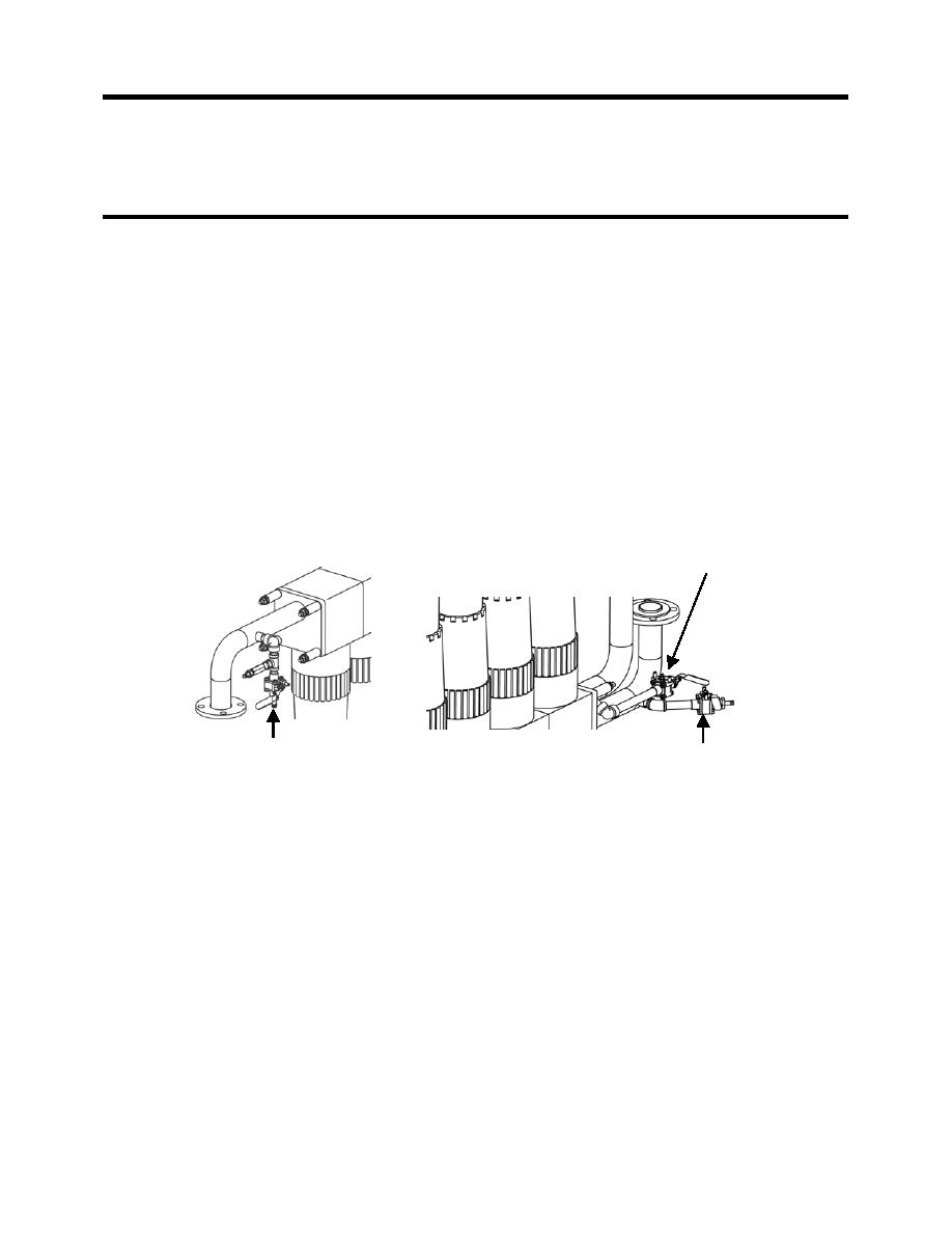
2. Open the following MF system vents/ drains (see Figure 4 for valve location):
a. Open MF Vent Valve V-114.
b. Open MF Filtrate Drain Valve V-203.
c. Open MF Shell Drain Valve V-403.
MF FILTRATE DRAIN VALVE V-203
MF VENT VALVE V-114
MF SHELL DRAIN VALVE V-403
Figure 4. MF Vent / Drain Valve Location.
MF Acid Cleaning
1. Set the waste hoses for acid cleaning as follows (see Figure 5):
a. Disconnect 4 x 6 in. Adaptor A-09 and the 6 in. red-banded waste out hose from the 4 in
x 5 ft. waste outlet hose of the TWPS
b. Check Adaptors A-10, A-12, and A-16 to make sure that there are gaskets inside the
female ends and that the gaskets are in good condition to ensure leak-tight connections.
c. Connect 4 x 2 in. Adaptor A-10 to the 4 in x 5 ft. waste outlet hose.
d. If using the cleaning waste storage tank, set up the hoses as follows (see Figure 5):
1) Connect a 2 in. x 10 ft., red-banded cleaning waste hose to Adaptor A-10.
2) Connect one or two additional 2 in. x 10 ft., red-banded hoses as needed to
reach the waste tank.
3) Connect Adaptor A-12 to the end of the last hose.
4) Connect Adaptor A-12 to the A-16 Adaptor on the waste tank with the female end
exposed and close the valves on these two adaptors.
5) Make sure Valve V-706 on the other Adaptor A-16 on the waste tank is closed.
0021 00-7


