ARMY TM 10-4610-309-14
MARINE CORPS TM10802A-14/1
0025 00
TACTICAL WATER PURIFICATION SYSTEM (TWPS)
OPERATOR INSTRUCTIONS
REVERSE OSMOSIS SYSTEM PRESERVATION OPERATION UNDER
USUAL CONDITIONS
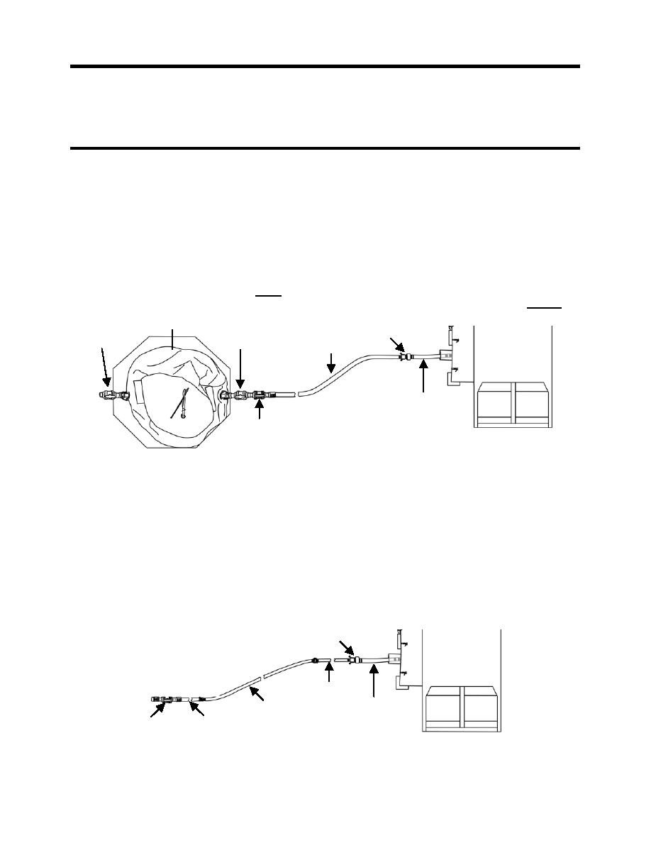
2. Make sure the cleaning waste hoses are set up as follows (see Figure 2):
a. Disconnect 4 x 6 in. Adaptor A-09 and the 6 in. red-banded waste out hose from the 4 in
x 5 ft. waste outlet hose of the TWPS
b. Connect 4 x 2 in. Adaptor A-10 to the 4 in x 5 ft. waste outlet hose.
c. If using the cleaning waste storage tank, set up the hoses as follows (see Figure 2):
1) Connect a 2 in. x 10 ft., red-banded cleaning waste hose to Adaptor A-10.
2) Connect one or two additional 2 in. x 10 ft., red-banded hoses as needed to
reach the waste tank.
3) Connect Adaptor A-12 to the end of the last hose.
4) Connect Adaptor A-12 to the A-16 Adaptor on the waste tank with the female end
exposed and open the valves on these two adaptors.
5) Make sure Valve V-706 on the other Adaptor A-16 on the waste tank is closed.
CLEANING WASTE TANK
A-16
A-16
A-10
TOP
VALVE V-706
VALVE V-706
2 X 10 S-HOSES
VIEW OF
TWPS
4 X 5 S-HOSE
A-12
VALVE V-705
Figure 2. Cleaning Waste Hose Set-Up with the Cleaning Waste Tank.
d. If not using the cleaning waste tank, set up the cleaning waste hoses as follows (see
Figure 3):
1) Connect a 2 x 10, red-banded, cleaning waste suction hose to Adaptor A-10.
2) Connect one 50-foot, green banded, raw water discharge hose to the 2 x10, red-
banded cleaning waste hose.
3) Connect one 2x10, red-banded, cleaning waste suction hose to the other end of
the 50-foot hose.
4) Connect Adaptor A-12 to the end of the second cleaning waste hose.
5) Open Adaptor A-12 Valve V-705.
6) Direct A-12 discharge into a depression in the ground away from the TWPS.
A-10
TOP
VIEW OF
TWPS
2 X 10 S-HOSE
4 X 5 S-HOSE
2 X 50 D-HOSE
A-12 VALVE V-705
2 X 10 S-HOSE
Figure 3. Cleaning Waste Hose Set-Up Without the Cleaning Waste Tank.
0025 00-3


