ARMY TM 10-4610-309-14
MARINE CORPS TM 10802A-14/1
TACTICAL WATER PURIFICATION SYSTEM (TWPS)
0034 00
TROUBLESHOOTING PROCEDURES
UNIT TROUBLESHOOTING PROCEDURES TACTICAL WATER
PURIFICATION SYSTEM (TWPS)
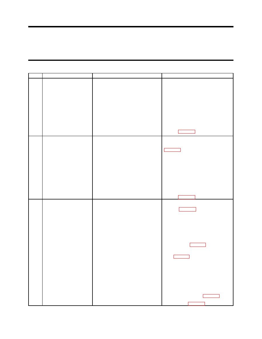
Table 13. Cold Weather System Troubleshooting Continued.
ITEM
MALFUNCTION
POSSIBLE CAUSES
CORRECTIVE ACTION
5
Heater cycles intermittently.
Remote thermostat (if used) set too low.
Set remote thermostat to a higher
temperature for more even operation.
Defective remote thermostat (if used).
Set the thermostat switch on the electric
control box to the "ON" position. If the
heater runs evenly, replace the remote
thermostat assembly.
Defective electrical supply or defective
Make sure the power cord is in good
electrical connections.
condition.
Defective overheat switch.
Test the overheat switch and replace if
defective (WP 0064).
6
Heater ignites but safety
Dirty or defective photocell.
Clean the photocell if dirty. Test the
control trips.
photocell and replace if defective
Duct overheat switch tripped
Push and hold Red Reset button for 2
minutes. Allow TWPS inside space to cool.
Restart. If the heater does not immediately
stop, but stops later due to a trip of the
safety control, reduce the thermostat setting
until the safety no longer trips. Do not run
the heater with outside temperature over 40
degrees F.
Defective overheat switch.
Test the overheat switch and replace if
defective (WP 0064).
7
All hose blankets and pump
Failure of Hose/Pump Heaters switch or
Open OCP display panel to expose the
heat collars remain cold with
PLC slot #1 input card.
sub-panel (WP 0060). Set Main CB to ON.
Hose/Pump Heaters switch
Set the Hose/Pump Heaters switch to ON.
ON.
Check the Slot #1 LED lights. If channel 13
is not ON:
1) Open the Slot #1 wire-way cover.
Locate the IN13 terminal. Check for
AC 110-volts between IN13 and
ground.
2) If voltage is found, replace the Slot #1
Input card (WP 0060).
3) If voltage is not found, replace the
Hose/Pump Heaters switch
Failure of PLC Slot #4 Output card or
Set the Hose/Pump Heaters switch OFF
failure of contactor K513 actuating coil.
and then ON. Listen for the contactor to
pull in. If not heard:
1) Open the Slot #4 wire-way cover.
Locate the O12 terminal. Check for
AC 110 volts between O12 and
ground.
2) If voltage is not found, replace the
Slot #4 output card (WP 0060).
3) If voltage is found, replace the
contactor (WP 0063).
0034 00-46


