ARMY TM 10-4610-309-14
MARINE CORPS TM 10802A-14/1
0057 00
TACTICAL WATER PURIFICATION SYSTEM (TWPS)
UNIT MAINTENANCE PROCEDURES
CHEMICAL INJECTION SYSTEM
b. Thread the new injection check valve assembly into the process pipe.
c. Make sure the discharge tubing is cut square.
d. Slide the new coupling nut over the discharge tubing so that the nut threads are facing
toward the end of the tubing.
e. Install the clamp ring about 1/4 inch onto the end of the tubing.
f. Insert the end of the discharge tube over the cone-shaped end of the valve housing.
g. Thread the coupling nut onto the valve housing and tighten hand-tight.
6. Start up the TWPS from Standby Shutdown and prime the pump as described in the Chemical
Injection Pump Replacement procedure earlier in this WP.
7. Observe the injection check valve to determine that it does not leak.
Foot Valve Assembly Replacement (V-611, V-621 and V-631):
Parts:
Foot valve assembly (TM 10-4610-309-24P)
Material:
Five-gallon bucket
Equipment Condition:
TWPS electric power "ON"
Replace a chemical injection pump foot valve assembly as follows:
1. Depressurize the chemical injection pump discharge tubing as described in the Chemical
Injection Pump Replacement procedure earlier in this WP.
1. Remove the foot valve and suction tubing from the chemical solution bucket and place it in the
empty five-gallon bucket to drain the suction line.
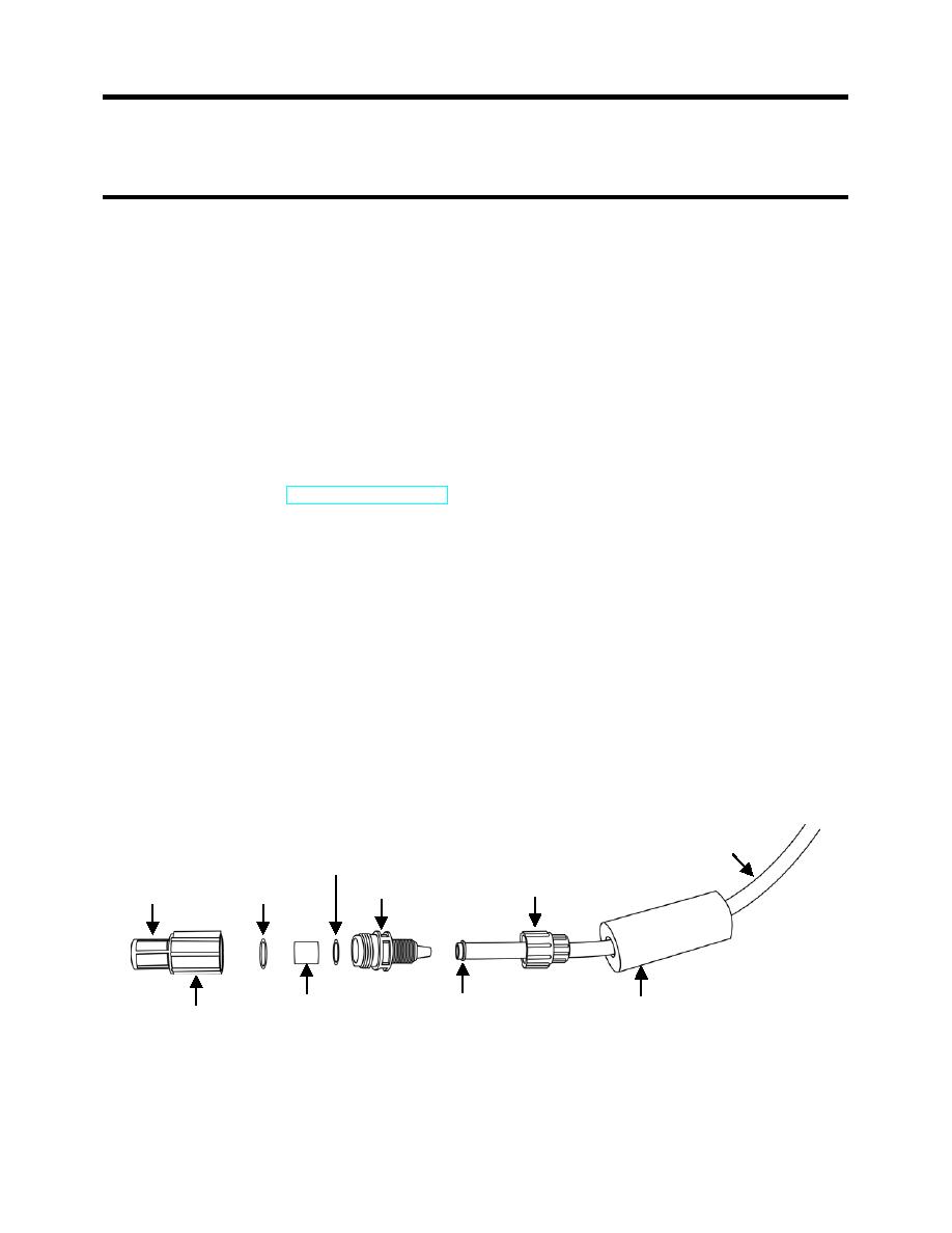
2. Remove the foot valve assembly from the suction tube as follows:
a. Unscrew the coupling nut from the foot valve housing and remove the foot valve
assembly from the suction tubing.
b. Remove the clamp ring and coupling nut from the suction tubing.
c. Discard the clamp ring, coupling nut, foot valve housing, flat washer, cartridge valve, O-
ring, foot valve seat, and foot valve screen.
SUCTION TUBE
FLAT WASHER
FOOT VALVE
COUPLING NUT
VALVE HOUSING
SCREEN
O-RING
CARTRIDGE VALVE
CLAMP RING
CERAMIC WEIGHT
FOOT VALVE
SEAT
Figure 7. Foot Valve Assembly Replacement.
0057 00-9


