ARMY TM 10-4610-309-14
MARINE CORPS TM 10802A-14/1
0057 00
TACTICAL WATER PURIFICATION SYSTEM (TWPS)
UNIT MAINTENANCE PROCEDURES
CHEMICAL INJECTION SYSTEM
e. Remove the four bolts and washers that secure the pump head to the chemical injection
pump drive assembly and remove the pump head assembly (see Figure 9).
f. Remove the pump diaphragm from the spacer by carefully grasping the outer edge of the
diaphragm and turning it counter-clockwise (see Figure 11).
SIZE CODE MARKING
PUMP DIAPHRAGM
SIZE CODE MARKING
DISK
RECESSED HOLE
SPACER ELECTROMAGNETIC POWER UNIT (E.P.U.)
Figure 11. Pump Diaphragm Removed from Pump Head Spacer.
2. Install the new pump diaphragm as follows (see Figure 11):
a. Check that the size code on the new diaphragm matches the size code on the on the
front of the disk.
b. Switch the main circuit breaker on the power distribution panel (PDP) to "ON".
c. Turn the pump switch on the operator control panel (OCP) to "ON".
d. Start the pump by turning the speed knob clockwise.
e. Turn the stroke knob to "90%".
f. With the pump stroking (running), screw on the new pump diaphragm clockwise until the
center begins to buckle inward, then stop the pump.
g. Turn the pump switch on the OCP to "OFF".
h. Switch the main circuit breaker on the PDP to "OFF".
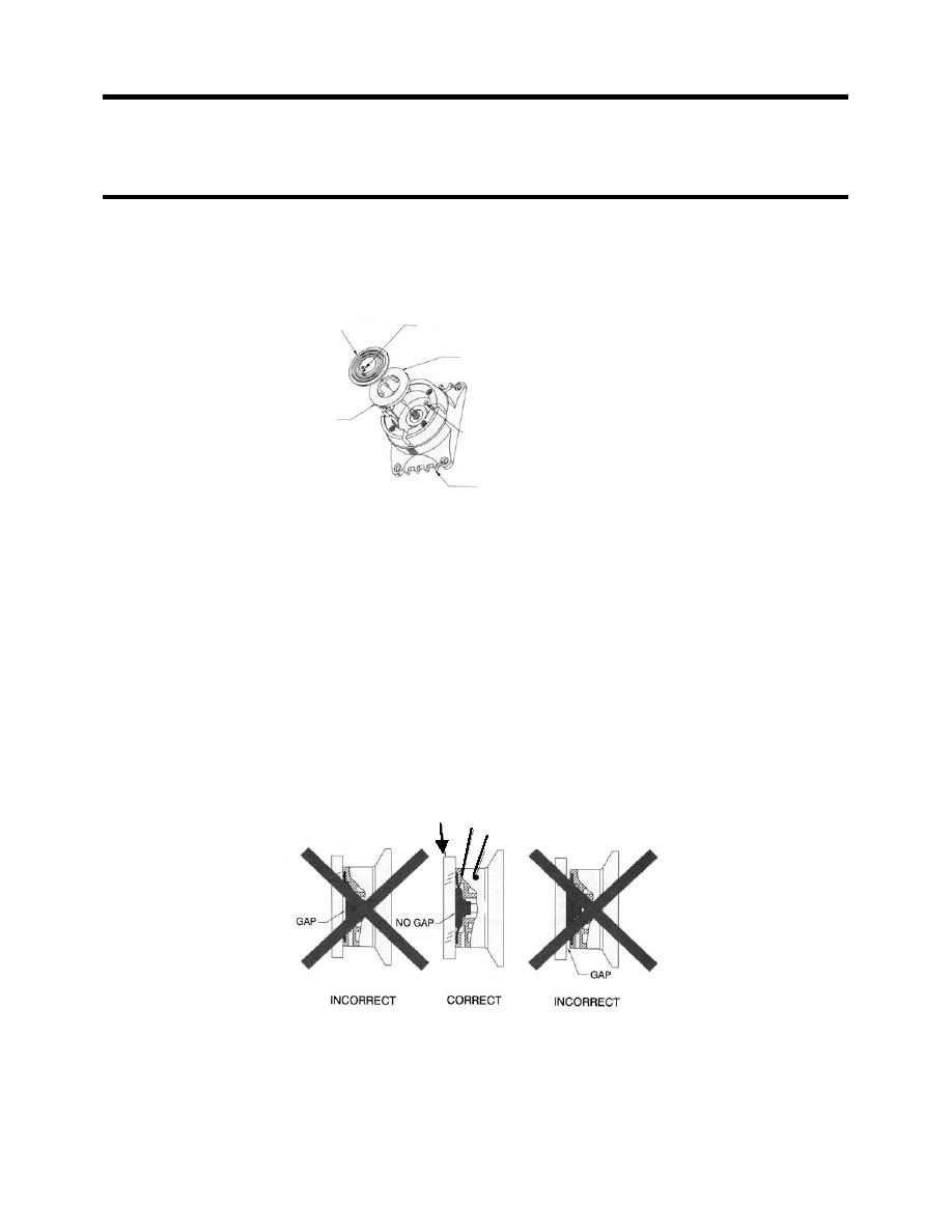
i. Grasp the outer edge of the diaphragm and screw it in or out as needed so that the
center of the diaphragm is flush with the outside edge of the spacer (see Figure 12).
STRAIGHT EDGE
PUMP DIAPHRAGM
SPACER
Figure 12. Diaphragm Positioning.
j.
Once the diaphragm is properly positioned, secure the pump head to the spacer using
the four screws.
k.
Tighten the four screws in a criss-cross pattern.
0057 00-14


