ARMY TM 10-4610-309-14
MARINE CORPS TM 10802A-14/1
0058 00
TACTICAL WATER PURIFICATION SYSTEM (TWPS)
UNIT MAINTENANCE PROCEDURES
PRODUCT WATER DISTRIBUTION SYSTEM
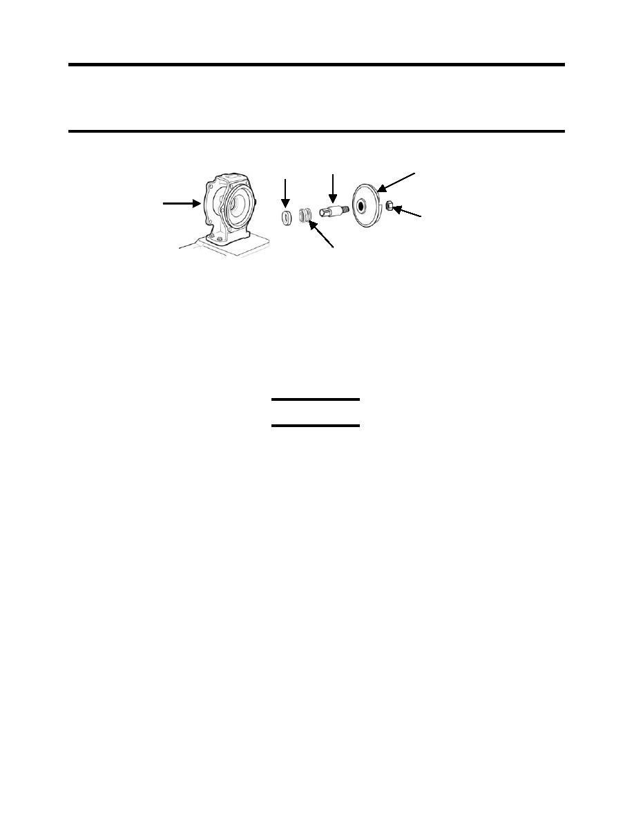
DRIVE SLEEVE
IMPELLER
SEAL SEAT
ADAPTER
IMPELLER LOCK NUT
SEAL ASSEMBLY
Figure 5. Drive Sleeve, Impeller, and Seal Assembly.
2. Install the new motor as follows:
a. If necessary, polish the new motor's drive shaft with fine abrasive cloth to remove any
rust or corrosion.
b. Attach the new motor to the adapter using the four cap screws and four lock washers.
c. Disconnect the motor cable from the old motor and attach it to the new motor. Refer to
REPLACE and P-7 Pump Motor Cable.
d. Lubricate the motor drive shaft and the inside diameter of the drive sleeve with corrosion
preventive compound.
CAUTION
Improper assembly can result in damage to the drive sleeve and the motor drive
shaft. Do NOT place a key between the drive shaft and the sleeve. Do NOT force
the drive sleeve onto the shaft. Failure to observe this caution can make impeller
clearance adjustments and the future removal of the drive sleeve difficult, and may
result in damage to the drive sleeve and/or the motor drive shaft.
e. Slide the drive sleeve and impeller assembly onto the drive shaft.
NOTE
If the sleeve does not easily slide onto the shaft, it may be necessary to remove
burrs from the shaft.
f. Install the coupling clamp assembly but do not tighten it.
g. Place a new housing gasket between the adapter and the pump housing.
h. Fit the pump onto the adapter and thread a nut on two opposing threaded studs to secure
the pump to the adapter. Tighten the two nuts.
3. Set the gap between the impeller and the pump wear plate as follows (see Figure 6):
a. Remove the four cap screws and 4 lock washers that secure the outlet flange to the
pump housing.
b. Carefully remove the pump flange to avoid damaging the gasket between the flange and
the pump housing.
c. If the gasket is damaged, replace it.
d. Look through the outlet into the pump. Turn the impeller drive sleeve and impeller by
hand until you see the impeller near the wear plate.
e. Insert a 0.015 inch feeler gauge between the impeller and wear plate. Move the
impeller forward or backward as needed to provide a gap of 0.015 to 0.017-inch.
0058 00-9


