TM 5-3800-205-10-2
AIR TRANSPORT BY C-130 AIRCRAFT - CONTINUED
0017 00
RETURN MACHINE TO OPERATIONAL CONFIGURATION - CONTINUED
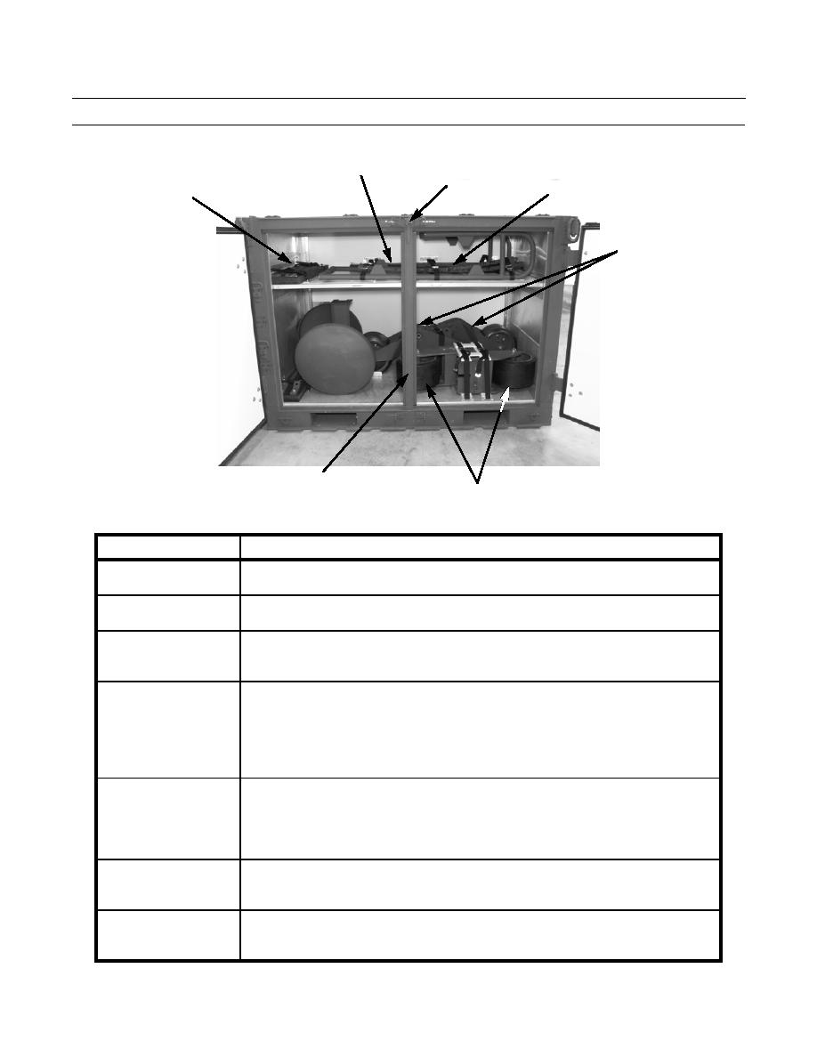
PRY BAR AND
TORQUE WRENCH CENTER POST
RETAINER
LOAD TRANSFER RELIEF
TURNBUCKLES
VALVE AND HOSE ASSEMBLY
LOAD
TRANSFER
AXLES
390-1118
CONTAINER CENTER POST
CUTTING EDGE WHEELS
Table 4. Stowage Instructions for ISU-60 Container - Two-Door End.
COMPONENT
STOWAGE INSTRUCTIONS
Pry Bar and Torque
1.
Place each component in cushion pad on shelf, against back wall of container.
Wrench
2.
Secure components with three straps.
Turnbuckles
1.
Place in cushion pad on left side of shelf.
2.
Secure with two straps.
1.
Place relief valve and hose assembly on top of ladder.
Load Transfer Relief
2.
Secure components with three straps.
Valve and Hose Assem-
bly
Load Transfer Axles
1.
Place one axle along back wall of container, with wheel facing right and other end
of axle resting in U-bracket on floor of container.
2.
Place second axle alongside first, but in reverse orientation. End of second axle
rests in second U-bracket on floor of container.
3.
Secure each axle to floor of container with a pin assembly through holes in U-
brackets. Secure each pin assembly with a lockpin.
Cutting Edge Wheels
1.
Place two straps through loops on floor, on right side of container.
2.
Place one cutting edge wheel on its side with wheel facing left.
3.
Place other cutting edge wheel in front of first, with wheel facing right.
4.
Place H-shaped bracket on top and pass two straps through bracket.
5.
Tighten straps.
Container Center Post
1.
Position center post, installing bottom end first.
2.
Raise shelf slightly to lock center post in position.
3.
Install center post retainer and tighten.
CAUTION
Check to ensure all components are securely fastened prior to closing and
securing door. Failure to do so may result in damage to equipment.
0017 00-47


