
(2) Position the assembled manifold assembly (3) on the four mounting studs (9) and secure with four
lockwashers (7) and nuts (6).
(3) Connect the carburetor fuel line (para. 68) and choke control (para. 68).
(4) Install the cylinder head housing, shrouding and heat deflectors (para.8).
(5) Install the canopy (para. 68).
107. Cylinder Heads
a. Description. Each of the L-type cylinder heads is secured to the cylinder block with seventeen
capscrews and plain washers. The cylinder heads must be removed if it is necessary to grind the valves or do
work on the pistons and connecting rods.
b. Removal.
(1) Remove the canopy (para. 68), cylin-
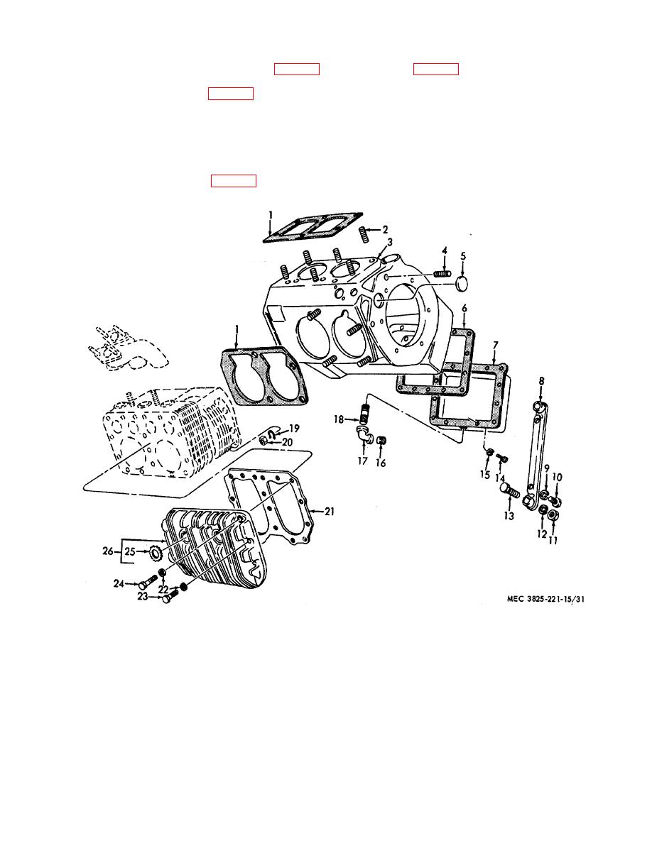
1
Gasket, cyl. base
10
Capscrew
19
Lockwasher
2
Stud
11
Nut
20
Nut
3
12
Lockwasher
21
Cylinder head gasket
4
Plug
13
Capscrew
22
Plain washer
5
Plug, expansion
14
Capscrew
23
Capscrew
6
Gasket
15
Lockwasher
24
Capscrew
7
Oil pan
16
Plug
25
Insert, spark plug
8
Engine support
17
Elbow
26
Cylinder head
9
Lockwasher
18
Nipple
Figure 31.
Crank case assembly.
AGO 6871A
59