TM 5-4610-223-12
1.
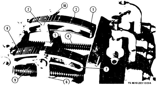
Calcium hypochlorite
5.
Ferric chloride feed
lever arm
indicator FEI-7
2.
Calcium hypochlorite
6.
Ferric chloride driving arm
feed indicator, FEI-8
7.
Ferric chloride lever arm
3.
Calcium hypochlorite
8.
Ferric chloride feed scale
feed scale
9.
Wingnut, 5/16-18 (2 reqd)
4.
Diaphragm pushrod and
10. Calcium hypochlorite driving
spring (2 reqd)
arm
Figure 2-5. Chemical Solution Feeder Controls.
k. Chemical Solution Feeder Controls and Indicators (Raider Model only).
(1)
Ferric Chloride Control Knob. The ferric chloride control knob (1, fig. 2-5.1) is located on the right side of
the chemical solution feeder assembly and regulates flow of ferric chloride solution to the erdolator tank. Setting of the
control knob must be determined by testing the treated water.
(2)
Calcium Hypochlorite Control Knob (Raider Model only). The calcium hypochlorite control knob (6, fig. 2-
5.1) is located on the left side of the chemical solution feeder assembly and regulates flow of calcium hypochlorite
solution to the erdolator tank. Setting of the control knob must be determined by testing the treated water.
2-3. INSTALLATION AND SETTING UP INSTRUCTIONS.
a.
General. The water purification set is constructed for movement over rough terrain as well as smooth hard
roads. Areas traveled are limited only by the capability of the truck and trailer on which the set is mounted.
Change 4 2-13