Chain Container
1.
Remove the loose end screw, lockwasher, plain
washer and loose end link from the hoist, see
Figure 2.
These parts are not required for installation of
the chain container.
2.
Insert loose end of chain through chute and into
bucket as shown in Figure 10.
3.
Place lockwasher on shouldered screw.
4.
With the shouldered screw through bracket and
chute, insert screw in the loose end screw hole
and firmly tighten the screw.
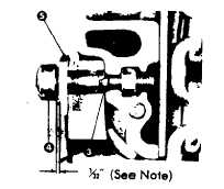
NOTE: There must be approximately %2"
clearance between the bracket and head of the
screw, as shown below, to allow the bracket to
rotate on the screw. During normal hoist
operation, the chain container swings freely
back and forth. If the bracket is not free to
rotate on the screw; the normal movement of
the chain container may cause the screw to
back-out.
5.
The chain must be loose and hang straight down
into bucket with a minimum of eight links
showing below bottom of hoist when hook is at
low position for Models A thru H and A-2 thru H-
2, and ten links showing for Models J thru RR
and J-2 thru RR-2. To obtain this setting may
require adjustment of the lower limit switch, see
page 17.
6.
Set the uppermost point of hook travel just
below bottom of chain bucket by adjusting the
upper limit switch, see page 16.
Under no condition should hook or load be
permitted to come into contact with the chain
container. If contact is permitted, the chain
container function can be interferred with and its
fasteners imperiled.
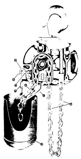
FIGURE 10. ATTACHING CHAIN CONTAINER.
(Models E, H, E-2 and H-2 illustrated)
(Models R, RR, R-2 and RR-2 similar)
1.
Chute
5.
Bracket
2.
Bucket
6.
Load Chain
3.
Lockwasher
7.
Bucket Support Links
4.
Shouldered Screw
(Do not order parts by these numbers. See parts list.)
NOTE: The Chain Container furnished by CM is
engineered and designed for use with a Lodestar hoist
of specific size and lift. Hoist malfunction and damage
to the unit can occur if other than properly engineered
Chain Container is used.
10


