THEORY OF OPERATION
The HDC uses a unique double spool arrangement that
serves to separate the null deadband from the feedback,
giving both safety against null drift and quick dynamic
response to command changes.
The command signal for the MCV106A is usually a
remote hydraulic control handle, as shown in Figure 2,
although other pressure sources could be used. The
handle modulates supply pressure from the pump (or
another source) so as to apply a proportional differential
pressure across the C1 and C2 input ports.
The HDC's null adjust is set with the modulating spring
compressed to the equivalent of 12, 120 or 217 psi,
depending on the output characteristics of the command
source, representing the differential pressure required to
move the actuator spool one direction or the other. This
is a factory setting that defines the width of the actuator
INSTALLATION
A highly reliable connection between the swashplate and
the drag link is necessary for safe operation. An
unreliable connection may result in loss of feedback with
a resulting loss of control. Series 3X pumps meet this
requirement, but all Series 2X units not already
equipped with an HDC or EDC must be retrofitted with
the appropriate drag link, press fit pin and retaining ring,
replacing the slip fit headless pin and E-rings used to
attach the original drag link.
Series 3X pumps with serial numbers of 82-34-00000 or
greater will accept the HDC without modification of the
pump. These units have a clearance notch cast into the
swashplate that provides additional room for link
movement. Series 3X pumps with serial numbers of
less than 82-33-99999 may not be fitted with the HDC
without modification of the swashplate by Sundstrand.
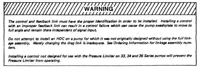
Prior to mounting any control on a pump, ensure that
both the control and the feedback link are correct for the
pump as evidenced by the series number stamped on
the link and the part number labeled on the control body.
See Table A, below.
spool deadband and cannot be changed in the field. By
tightening or loosening the null adjust screw, the fixed
deadband is moved toward or away from the "A"' control
port in order to null the valve.
As differential control pressure (C1-C2) rises beyond the
deadband, the actuator spool moves in one direction or
the other, pivoting the crosslink about its center. The
pivoting crosslink pushes or pulls the porting spool in the
opposite direction of the actuator spool. When the
porting spool has moved far enough to open A or B to
supply pressure, oil is ported to the pump servocylinders
to move the swashplate. As the swashplate moves, the
feedback link follows, pivoting the crosslink about the
stationary end of the actuator spool, driving the porting
spool back to its neutral position. Because the feedback
signal is entered into the control loop after the command
has been input, response time and accuracy are
enhanced.
TABLE A
Table A correlates the pump series number with the
series number stamped on the side of the feedback
link protruding from the control.
SERIES
LINK MARKING
20
20 No Spacer
21, 22
21, 22
23
23
24
24
25
25
26
26
27
27
33, 34, 36
33, 34, 36
Sundstrand Mobile Controls
3