DECKMASTER
PUMP NEUTRAL ADJUSTMENT ( continued from
page 6)
•7.
If the transmission operates as shown by motor
shaft rotation, reduce sped to idle. Using a 3/16
inch internal hex wrench, slowly turn the null
adjustment
screw
clockwise
or
counterclockwise
until the transmission
does not operate. Repeat step 6 Note that
charge pressure should drop approximately 20
psi with forward or reverse stroking of the pump
washplate due to the shifting of the shuttle valve
in the motor manifold.
•8.
With a 3/16-inch internal hex wrench, slowly
turn the null adjustment screw clockwise
until charge pressure begins to decrease. Then
slowly
turn
the
adjustment
screw
counterclockwise
, observing the angle of
rotation, until charge pressure decreases again
(charge pressure will rise in neutral and drop
when going into stroke).
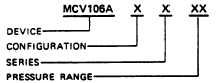
ORDERING INFORMATION
A range of options to the basic HDC allows it to be
custom tailored to each application. The control is
specified by filling in each slot of the order number, as is
shown in Table B, with the appropriate model code.
Other options are possible. Consult Sundstrand Mobile
Controls with further questions.
TABLE B. INFORMATION NECESSARY TO SPECIFY
THE HYDRAULIC DISPLACEMENT CONTROL
1.
DEVICE IDENTITY
This is the basic HDC. The model code is
MCV106A.
2
CONFIGURATION (including assembly kit)
PRESURE
WITH
MODEL
LIMITER OR
ANNULAR
CODE
PRESSURE
CONTROL
OVERRIDE
5
NO*
NO
8
NO
YES
7
YES**
NO
8
YES*
YES
*PRESSURE OVERRIDE ONLY
**MODEL CODE 7 DEVICES MAY NOT BE USED ON
SERIES 3X PUMPS IF ORDERED LESS LINKAGE
ASSEMBLY ("9" UNDER THE SERIES PARAMETER).
•9.
Turn the adjustment screw clockwise
half
the amount of the turn observed in step 8. This
should be the center of neutral.
•10.
Hold the adjustment screw and securely tighten
the hex lock nut on the adjustment screw to 14-
18 foot-pounds. Note that if a motor is used
which does not have a manifold, neutral should
be adjusted (steps 8.10) by observing the motor
output shaft rotation without a load.
•11.
Stop the prime mover.
•12.
Run the system briefly to ensure that it operates
proportionally
on
both
sides
of
the
null
command. Swashplate movement can be
verified
by
watching
movement
of
the
swashplate feedback shaft, shown in Figure 1.
The Pressure Override and Pressure Limiter accomplish
the same function-they shift the pump swashplate
toward neutral when system pressure crosses a pre-set
threshold. They thus limit system pressure, protect
components from heat generated by flow across relief
valves and conserve pump horsepower. Pressure
override is available only for Series 2X pumps, and
pressure limiting is available only for Series 3X pumps.
Pressure limiting and annular control are not available
together. If the model code chosen indicates that the
pressure override/pressure limiting function is desired
(i.e., "yes" is chosen in the second column of the
configuration parameter, above), only pressure limiting
will be provided directly by Soundstrand Mobile
Controls (pressure limiting is accomplished using a
different porting spool); the Pressure Override Valve
must
be
obtained
through
Sundstrand
Hydrotransmission. See below.
Stroke controls with annular control have a groove cut
into the spool bore of the housing that allows for higher
flow from the control ports when they are uncovered,
increasing swashplate response.
Kits are needed in order to install the HDC onto the
pump. Which kit is shipped with the HDC depends on
which pump series is ordered. Included in the kit are:
retaining rings, swashplate pin, drag link, orifice, hex
screws, O-rings and gasket In some cases not all of the
above are necessary for installation and they are not
included with the kit. Individual drag links will not be
supplied by Sundstrand. Consult Mobile Controls for
replacement parts-
ORDERING INFORMATION