T M 1 0 - 4 6 1 0 - 2 3 2 - 12
Table 4-2. Unit Troubleshooting Guide (Continued)
MALFUNCTION
TEST OR INSPECTION
CORRECTIVE ACTION
Step 4.
Step 5.
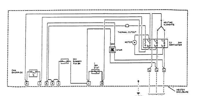
Figure 4-1. Electric Heater Wiring Diagram
Open the Metal Oxide Varistor (MOV) junction box. Check MOV Nos. 25,26, and 27 for physical dam-
age or signs of shorting. Remove wire Nos. HL1, HL2, and HL3 from the MOV terminals. Reference
Interconnection Diagram FO-2, sheet 16). Use a multimeter and check for continuity from the termi-
nals which the wires were onto ground.
(a) Repair any damaged or loose wires (para. 4-76).
(b) Replace any MOV which is physically damaged or shows continuity to ground from the power
terminal (para. 4-76).
(c) Replace any damaged wire harness in the pump skid junction box (para. 4-76).
Open the acess panel on the heater. Tag and disconnect the four incoming power leads. Check con-
Interconnection Diagram FO-2, sheet 16). Check each lead for shorts between phases and shorts to
the ground wire. The reading should be infinity for each check.
(a) Replace the cable if-it shows open during continuity checks (para. 4-77).
(b) Replace the cable if it shows a short between phases or a short to ground (para. 4-77).
(c) Notify direct support maintenance if the above checks have not located the problem.
2. Electric heater fan runs but there is no heat.
Step 1. Check that fan heat switch is turned to heat.
Change 1
4-39
tinuity, point-to-point, from P66A to HL1, P66B to HL2, P66C to HL3, and P66D to HL0 (Reference