TM 10-4610-239-10
TM 08580B-10/1
CHAPTER 2
OPERATING INSTRUCTIONS
SECTION I. DESCRIPTION AND USE OF OPERATOR’S CONTROLS AND INDICATORS
2-1.
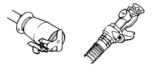
CONTROLS AND INDICATORS (TRAILER). (Army) The only indicators on the flatbed trailer are the stop lights,
tail lights, and the blackout light. These lights are powered and controlled from the towing vehicle through a trailer cable.
The plug on the cable (fig. 2-1) and the receptacle makes the system operational. The two air hoses connect to the
towing vehicle brake system with glad-hand connectors (fig. 2-2). When the trailer is not connected to the towing vehicle,
the connectors are stowed on dummy couplers on the trailer to prevent damage and contamination.
CAUTION
Do not attempt to move trailer without releasing airbrakes; this requires 90-130 psi air pressure applied to
air hoses.
2-2.
BRAKE SYSTEM. (Army) The service brakes are air-actuated, and the controls are in and part of the towing
vehicle. When the two air hoses from the trailer are connected to the connectors on the towing vehicle, the service brake
system and the brake pedal on the towing vehicle automatically operate the trailer brakes. An air tank mounted under the
trailer frame serves as a reservoir for the operation of the service brake system when the air hoses are disconnected from
the towing vehicle. Disconnecting the air hoses causes the service brakes to engage automatically, thus serving as
parking brakes for the trailer. Should the air supply from both the towing vehicle and the trailer reservoir be interrupted, a
compression spring immediately locks the brakes. See fig. 2-82 for procedure for resetting locked spring brake.
2-1
Figure 2-1. Electrical Plug
Figure 2-2. Air Hose Glad-Hand Connectors