TM 10-4610-240-10
TM 08580C-10/1
T.O. 40W4-13-21
1.
MULTIMEDIA FILTER
2.
R.O. PRESSURE VESSELS
3.
R.O. PUMP
4.
CONTROLPANEL
5.
CARTRIDGE FILTER
6
PULSE DAMPENER
7.
BOOSTER PUMP
8.
GENERATOR PLATFORM (ARMY)
9.
PRIME/RUN VALVES
10.
CHEMICAL FEED PUMP
11.
CHEMICALFEED
CONTAINERS/RACK
NOTE
Illustration denotes Army ROWPU MC and AF units are skid-mounted with no generator
platform.
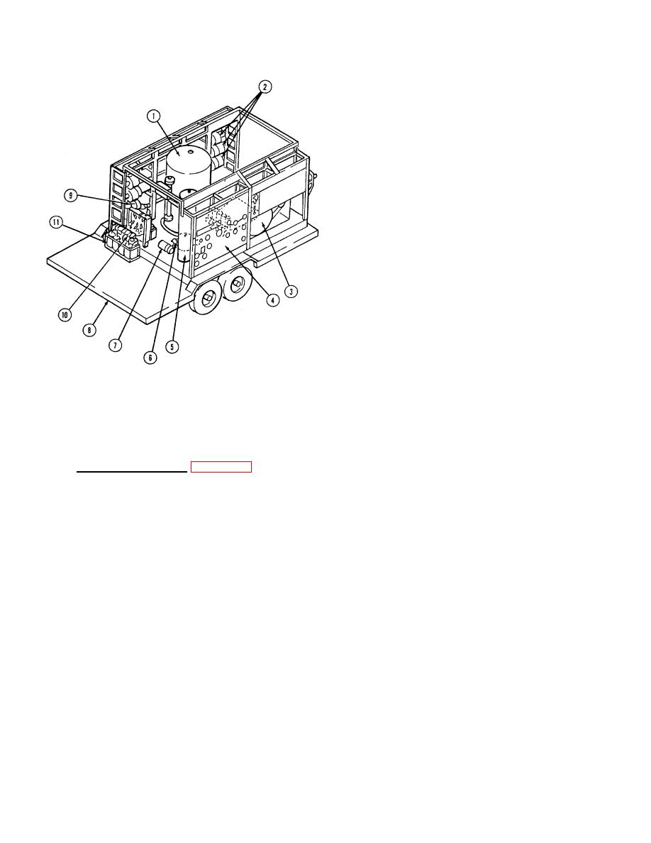
FIGURE 1-13. ROWPU GENERATOR REMOVED (REAR VIEW)
e. Additional Components. Figure 1-13 identifies the following parts:
MULTIMEDIA FILTER (1). Provides first stages of removing matter from raw water.
R.O. PRESSURE VESSELS (2). Loaded with rolled, thin films (called elements). here, osmosis is
reversed by applying pressure to reduce dissolved solids from raw filtered water.
R.O. PUMP (3). Applies high pressure to raw filtered water flowing through R.O. pressure vessels.
CONTROL PANEL (4). Panel on the control box assembly with meters, gauges, control valves, hose
connections, and electrical switches.
CARTRIDGE FILTER (5). Provides cleaning to waiter coming out of the multimedia filter.
PULSE DAMPENER (6). Located behind the cartridge filter, reduces shock (water pulses) caused by
R.O. pump.
1-12


