TM 10-4610-240-10
TM 08580C-10/1
T.O. 40W4-13-21
(d) If product water tank is full, stop
(12) Watch water level in product water tanks.
ROWPU until more water is needed. (See paragraph 2-
14 for
(a) Keep tanks covered.
normal shutdown procedure.)
(b) To distribute water, start distribution
pump.
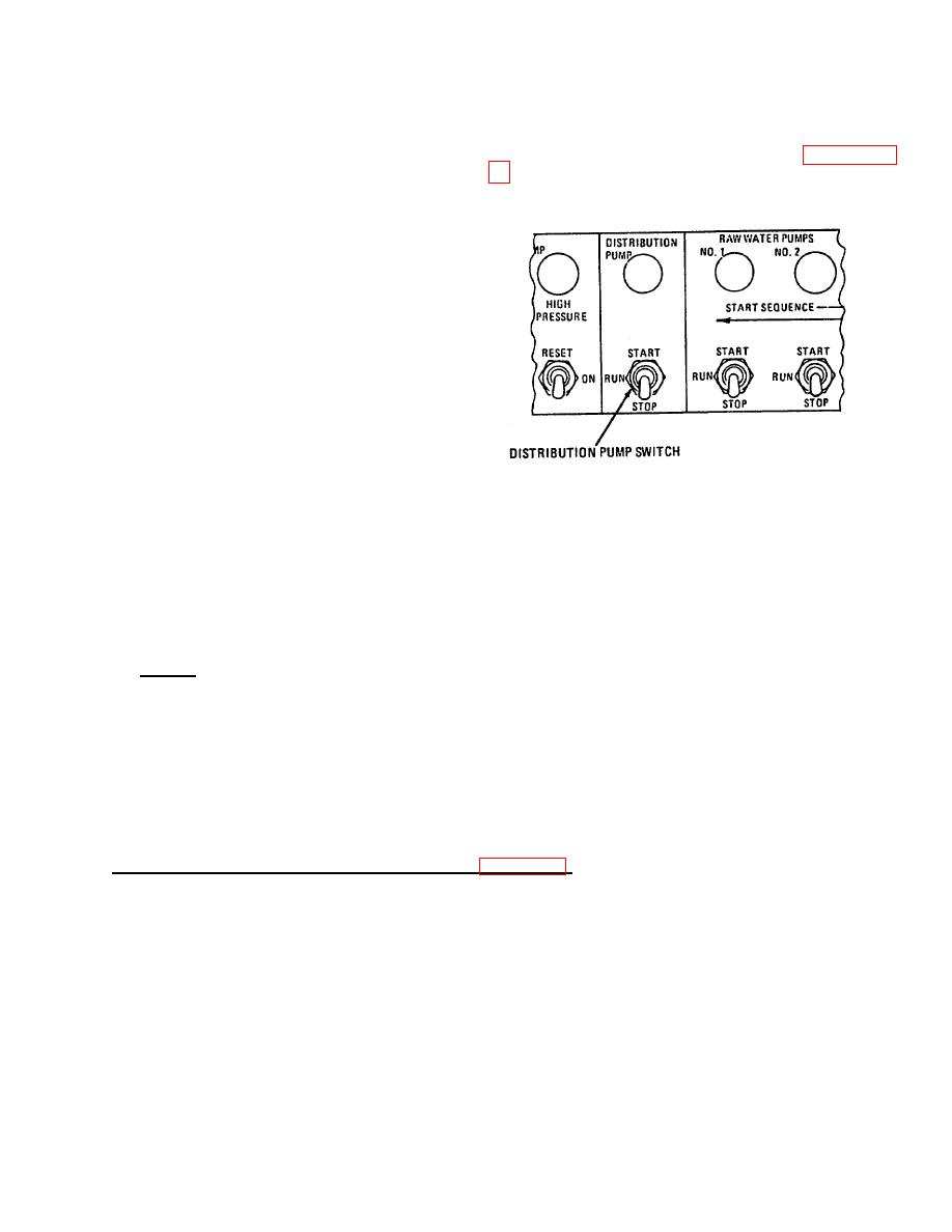
(13) To start distribution pump, proceed as
follows:
(a) Set DISTRIBUTION PUMP switch on
control box assembly panel to START.
(b) Lamp comes on.
(c) Run distribution pump until user has
enough water, then switch to STOP.
FIGURE 2-69. DISTRIBUTION PUMP SWITCH
2-10. BACKWASH OF MULTIMEDIA FILTER.
NOTE
The multimedia filter should be backwashed:
After 20 hours of ROWP'U operation, or
Multimedia filter gage reading is over 10 psid, or
Multimedia filter gage reading exceeds 5 psid of log reading at startup, or
ROWPU is to be shut down.
a.
General. The backwash cycle is an up-flow operation. Water flows from the bottom to the top of the tank
and then out to drain through the backwash flow control, washing out turbidity and settling the filter bed. The filter has
five separate backwash stages. The first stage of backwash is at approximately 70 gpm to fluidize the bed. A second
backwash stage begins at approximately 120 gpm, tumbles at the bed, and scours the particles against one another when
the backwash diaphragm valve opens. The backwash diaphragm valve then closes, returning the backwash rate to
approximately 70 gpm to restratify the media bed. The rinse cycle is a down flow operation. Water flows from the top of
the tank through the filter bed and out to drain. This displaces the backwash water in the tank, and preconditions the
filter bed before the filter reaches the purge cycle. The purge cycle is rapid downflow rinse to remove turbidity from the
bottom of the filter and recondition the filter bed prior to the return to service
b. Backwash Timer and Multimedia Filter Control Valve (figure 2-14).
The direction and rate of water flow through the multimedia filter are controlled by the control valve and backwash
diaphragm valve. The control valve consists of six diaphragms which open and close during the timer cycles of
backwash, conditioned rinse, and service (service means normal ROWPU operation). As the backwash timer
automatically changes cycles, its pilot valve changes position. When the backwash timer pilot valve changes position, it
hydraulically closes and opens the diaphragms in the control valve. During the 120 gpm portion of the backwash cycle
(referred to as "fast backwash") the backwash timer solenoid valve sends water to the backwash diaphragm valve
(located just under the control valve). This opens the backwash diaphragm valve, resulting in the higher rate of
backwash water flow.
2-69


