TM 10-4610-310-14
UNIT MAINTENANCE
LIGHTWEIGHT WATER PURIFIER
TROUBLESHOOTING PROCEDURES
CONTROL MODULE
SWITCHES
General
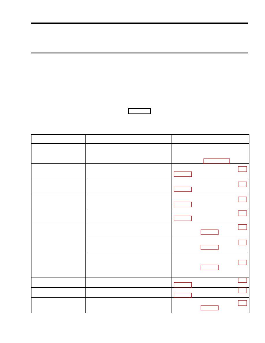
The table lists the common malfunctions that you may find during the operation or maintenance of the switches
on the control module used in Lightweight Water Purifier (LWP). The back panel may need to be removed to
access the switches and associating wires. You should perform the tests/inspections and corrective actions in
the order listed.
This manual cannot list all malfunctions that may occur, nor all tests or inspections and corrective actions. If a
malfunction is not listed or is not corrected by listed corrective actions, notify your supervisor.
WARNING
When checking for voltage on an energized component, extreme care must be taken. Only qualified and
authorized electrician should maintain, troubleshoot, and operate energized equipment. Injury or death to
personnel may result.
MALFUNCTION
TEST / INSPECTION
CORRECTIVE ACTION
If not present inspect wire 2 for loose
Test for power supply; ensure 120 VAC is
connection, breaks and continuity.
1. Any malfunctioning
present across wire 2 at the particular
Troubleshoot control module power
switches
switch and ground.
supply (WP 0030 00)
2. Mode selector switch
Place the switch to BACKWASH. Test for
If not present; replace the switch. WP
(backwash mode
120 VAC across wire 8 at the switch and
malfunction)
ground.
3. Mode selector switch
Place the switch to FAST FLUSH. Test for
If not present; replace the switch. WP
(fast flush mode
120 VAC across wire 9 at the switch and
malfunction)
ground.
4. Mode selector switch
Place the switch to MAINTENANCE. Test
If not present; replace the switch. WP
(maintenance mode
for 120 VAC across wire 10 at the switch
malfunction)
and ground.
5. Raw water pump
Place the switch to ON. Test for 120 VAC
If not present; replace the switch. WP
switch
across wire 49 at the switch and ground.
Place the switch to HAND. Test for 120
If not present; replace the switch. WP
VAC across wire 46 and 3 and also
across wire 48 and 3 at the switch.
Place the switch to AUTO. Place the raw
If not present; replace the switch. WP
water pump switch to ON. Test for 120
6. Chemical pump switch
VAC across wire 48 and 3 at the switch.
Place the switch to AUTO. Ensure there is
enough water in the filtrate tank for low-
If not present; replace the switch. WP
level switch to be engaged and input light
0 will be on at the PLC. Test for 120 VAC
across wire 46 and 3 at the switch.
Place the switch to ON. Test for 120 VAC
If not present; replace the switch. WP
7. Heater switch
across wire 11 at the switch and ground.
8. Distribution pump
Place the switch to ON. Test for 120 VAC
If not present; replace the switch. WP
switch
across wire 50 at the switch and ground.
Place the switch to HAND. Test for 120
If not present; replace the switch. WP
9. Backwash pump switch
VAC across wire 44 and ground at the
switch.
0070 00-1


